

498
Digital Electronics
111
110
101
100
011
010
001
000
0
1
2
3
4
5
6
7
Analog Input (V)
t
u p
t u
O
l
a
t i
g
i
D
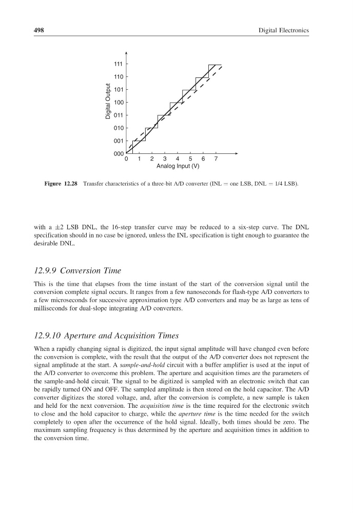
Figure 12.28 Transfer characteristics of a three-bit A/D converter (INL = one LSB, DNL = 1/4 LSB).
with a ±2 LSB DNL, the 16-step transfer curve may be reduced to a six-step curve. The DNL
specification should in no case be ignored, unless the INL specification is tight enough to guarantee the
desirable DNL.
12.9.9 Conversion Time
This is the time that elapses from the time instant of the start of the conversion signal until the
conversion complete signal occurs. It ranges from a few nanoseconds for flash-type A/D converters to
a few microseconds for successive approximation type A/D converters and may be as large as tens of
milliseconds for dual-slope integrating A/D converters.
12.9.10 Aperture and Acquisition Times
When a rapidly changing signal is digitized, the input signal amplitude will have changed even before
the conversion is complete, with the result that the output of the A/D converter does not represent the
signal amplitude at the start. A sample-and-hold circuit with a buffer amplifier is used at the input of
the A/D converter to overcome this problem. The aperture and acquisition times are the parameters of
the sample-and-hold circuit. The signal to be digitized is sampled with an electronic switch that can
be rapidly turned ON and OFF. The sampled amplitude is then stored on the hold capacitor. The A/D
converter digitizes the stored voltage, and, after the conversion is complete, a new sample is taken
and held for the next conversion. The acquisition time is the time required for the electronic switch
to close and the hold capacitor to charge, while the aperture time is the time needed for the switch
completely to open after the occurrence of the hold signal. Ideally, both times should be zero. The
maximum sampling frequency is thus determined by the aperture and acquisition times in addition to
the conversion time.
Digital Electronics
111
110
101
100
011
010
001
000
0
1
2
3
4
5
6
7
Analog Input (V)
t
u p
t u
O
l
a
t i
g
i
D
Figure 12.28 Transfer characteristics of a three-bit A/D converter (INL = one LSB, DNL = 1/4 LSB).
with a ±2 LSB DNL, the 16-step transfer curve may be reduced to a six-step curve. The DNL
specification should in no case be ignored, unless the INL specification is tight enough to guarantee the
desirable DNL.
12.9.9 Conversion Time
This is the time that elapses from the time instant of the start of the conversion signal until the
conversion complete signal occurs. It ranges from a few nanoseconds for flash-type A/D converters to
a few microseconds for successive approximation type A/D converters and may be as large as tens of
milliseconds for dual-slope integrating A/D converters.
12.9.10 Aperture and Acquisition Times
When a rapidly changing signal is digitized, the input signal amplitude will have changed even before
the conversion is complete, with the result that the output of the A/D converter does not represent the
signal amplitude at the start. A sample-and-hold circuit with a buffer amplifier is used at the input of
the A/D converter to overcome this problem. The aperture and acquisition times are the parameters of
the sample-and-hold circuit. The signal to be digitized is sampled with an electronic switch that can
be rapidly turned ON and OFF. The sampled amplitude is then stored on the hold capacitor. The A/D
converter digitizes the stored voltage, and, after the conversion is complete, a new sample is taken
and held for the next conversion. The acquisition time is the time required for the electronic switch
to close and the hold capacitor to charge, while the aperture time is the time needed for the switch
completely to open after the occurrence of the hold signal. Ideally, both times should be zero. The
maximum sampling frequency is thus determined by the aperture and acquisition times in addition to
the conversion time.