

Data Conversion Circuits – D/A and A/D Converters
497
output can only identify 2
n output codes while there are an infinite number of analogue input values
adjacent to the LSB of the A/D converter that are assigned the same output code. For instance, if we
are digitizing an analogue signal with a peak value of 7 V using three bits, then all analogue voltages
equal to or greater than 5.5 V and less than or equal to 6.5 V will be represented by the same output
code, i.e. 110 (if the output coding is in straight binary form). The error is ±0.5 V or ±1/2 LSB, as
a one-LSB change in the output corresponds to an analogue change of 1 V in this case. The ±1/2
LSB limit to resolution is known as the fundamental quantization error. Expressed as a percentage, the
quantization error in an eight-bit converter is one part in 255 or 0.4 %.
12.9.7 Nonlinearity
The nonlinearity specification [also referred to as the integral nonlinearity (INL) by some
manufacturers] of an A/D converter describes its departure from a linear transfer curve. The nonlinearity
error does not include gain, offset and quantization errors. It is expressed as a percentage of full scale
or in LSBs.
12.9.8 Differential Nonlinearity
This indicates the worst-case difference between the actual analogue voltage change and the ideal
one-LSB voltage change. The DNL specification is as important as the INL specification, as an
A/D converter having a good INL specification may have a poor-quality transfer curve if the DNL
specification is poor. DNL is also expressed as a percentage of full scale or in LSBs. DNL in fact
explains the smoothness of the transfer characteristics and is thus of great importance to the user.
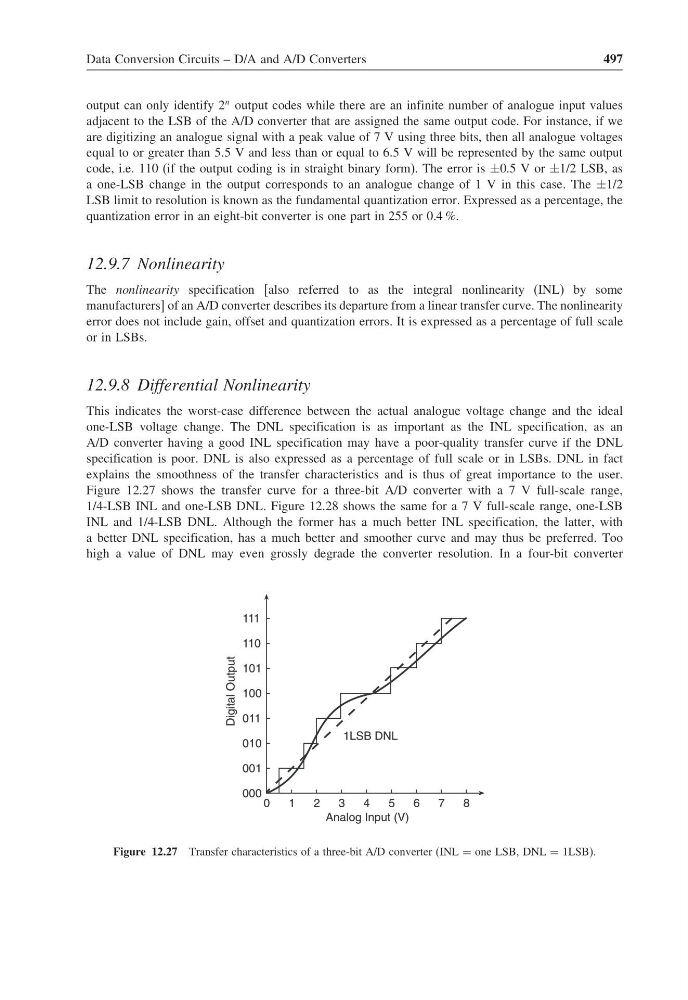
Figure 12.27 shows the transfer curve for a three-bit A/D converter with a 7 V full-scale range,
1/4-LSB INL and one-LSB DNL. Figure 12.28 shows the same for a 7 V full-scale range, one-LSB
INL and 1/4-LSB DNL. Although the former has a much better INL specification, the latter, with
a better DNL specification, has a much better and smoother curve and may thus be preferred. Too
high a value of DNL may even grossly degrade the converter resolution. In a four-bit converter
111
110
101
100
011
010
001
000
0
1
2
3
4
5
6
7
8
1LSB DNL
Analog Input (V)
t
u
p
t
u
O
l
a
t
i
g
i
D
Figure 12.27 Transfer characteristics of a three-bit A/D converter (INL = one LSB, DNL = 1LSB).
497
output can only identify 2
n output codes while there are an infinite number of analogue input values
adjacent to the LSB of the A/D converter that are assigned the same output code. For instance, if we
are digitizing an analogue signal with a peak value of 7 V using three bits, then all analogue voltages
equal to or greater than 5.5 V and less than or equal to 6.5 V will be represented by the same output
code, i.e. 110 (if the output coding is in straight binary form). The error is ±0.5 V or ±1/2 LSB, as
a one-LSB change in the output corresponds to an analogue change of 1 V in this case. The ±1/2
LSB limit to resolution is known as the fundamental quantization error. Expressed as a percentage, the
quantization error in an eight-bit converter is one part in 255 or 0.4 %.
12.9.7 Nonlinearity
The nonlinearity specification [also referred to as the integral nonlinearity (INL) by some
manufacturers] of an A/D converter describes its departure from a linear transfer curve. The nonlinearity
error does not include gain, offset and quantization errors. It is expressed as a percentage of full scale
or in LSBs.
12.9.8 Differential Nonlinearity
This indicates the worst-case difference between the actual analogue voltage change and the ideal
one-LSB voltage change. The DNL specification is as important as the INL specification, as an
A/D converter having a good INL specification may have a poor-quality transfer curve if the DNL
specification is poor. DNL is also expressed as a percentage of full scale or in LSBs. DNL in fact
explains the smoothness of the transfer characteristics and is thus of great importance to the user.
Figure 12.27 shows the transfer curve for a three-bit A/D converter with a 7 V full-scale range,
1/4-LSB INL and one-LSB DNL. Figure 12.28 shows the same for a 7 V full-scale range, one-LSB
INL and 1/4-LSB DNL. Although the former has a much better INL specification, the latter, with
a better DNL specification, has a much better and smoother curve and may thus be preferred. Too
high a value of DNL may even grossly degrade the converter resolution. In a four-bit converter
111
110
101
100
011
010
001
000
0
1
2
3
4
5
6
7
8
1LSB DNL
Analog Input (V)
t
u
p
t
u
O
l
a
t
i
g
i
D
Figure 12.27 Transfer characteristics of a three-bit A/D converter (INL = one LSB, DNL = 1LSB).