

494
Digital Electronics
R FB
V ref
Out 1
DAC
Out 2
−
+
A 2
R 3
R 1
V IN
−
+
V OUT
A 2
R 4
C
R 2
−
+
A 1
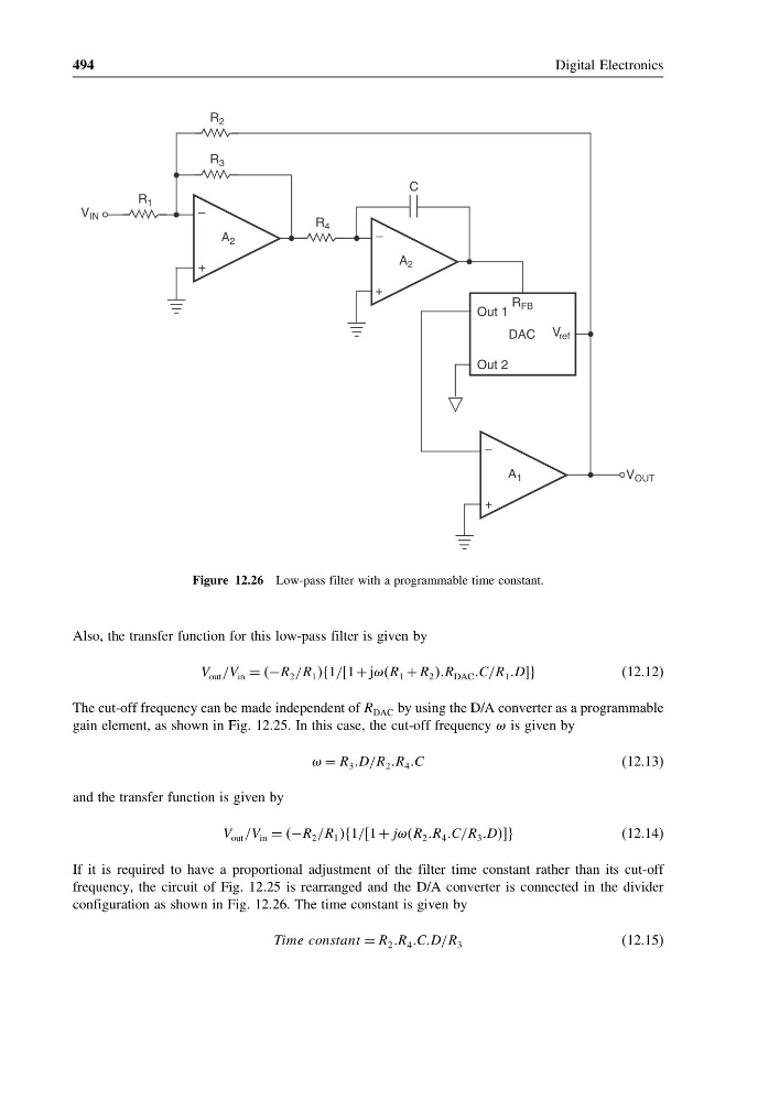
Figure 12.26 Low-pass filter with a programmable time constant.
Also, the transfer function for this low-pass filter is given by
V out /V in = −R 2 /R 1 1//1 + jR 1 + R 2 R DAC C/R 1 DDD
(12.12)
The cut-off frequency can be made independent of R DAC by using the D/A converter as a programmable
gain element, as shown in Fig. 12.25. In this case, the cut-off frequency is given by
= R 3 D/R 2 R 4 C
(12.13)
and the transfer function is given by
V out /V in = −R 2 /R 1 1//1 + jjjR 2 R 4 C/R 3 DDDD
(12.14)
If it is required to have a proportional adjustment of the filter time constant rather than its cut-off
frequency, the circuit of Fig. 12.25 is rearranged and the D/A converter is connected in the divider
configuration as shown in Fig. 12.26. The time constant is given by
Time constant = R 2 R 4 CCD/R 3
(12.15)
Digital Electronics
R FB
V ref
Out 1
DAC
Out 2
−
+
A 2
R 3
R 1
V IN
−
+
V OUT
A 2
R 4
C
R 2
−
+
A 1
Figure 12.26 Low-pass filter with a programmable time constant.
Also, the transfer function for this low-pass filter is given by
V out /V in = −R 2 /R 1 1//1 + jR 1 + R 2 R DAC C/R 1 DDD
(12.12)
The cut-off frequency can be made independent of R DAC by using the D/A converter as a programmable
gain element, as shown in Fig. 12.25. In this case, the cut-off frequency is given by
= R 3 D/R 2 R 4 C
(12.13)
and the transfer function is given by
V out /V in = −R 2 /R 1 1//1 + jjjR 2 R 4 C/R 3 DDDD
(12.14)
If it is required to have a proportional adjustment of the filter time constant rather than its cut-off
frequency, the circuit of Fig. 12.25 is rearranged and the D/A converter is connected in the divider
configuration as shown in Fig. 12.26. The time constant is given by
Time constant = R 2 R 4 CCD/R 3
(12.15)