

Data Conversion Circuits – D/A and A/D Converters
493
is determined by the settling time of the D/A converter, the required resolution and the permissible
quantization noise.
Since most of the functions are symmetric, it is usual to synthesize only half of the waveform and
then invert it for the second half. This is true for pulse, triangular, ramp and trapezoidal waveforms.
For sinusoidal waveforms it is necessary only to synthesize one-quarter of the waveform. In the
arrangement of Fig. 12.23, the frequency is determined by the clock frequency and the waveform by
the contents of the ROM.
12.7.5 Digitally Controlled Filters
Active filters having low noise and distortion with controllable gain, centre frequency and Q-factor can
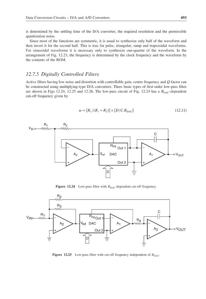
be constructed using multiplying-type D/A converters. Three basic types of first-order low-pass filter
are shown in Figs 12.24, 12.25 and 12.26. The low-pass circuit of Fig. 12.24 has a R DAC -dependent
cut-off frequency given by
= R 1 //R 1 + R 2 × D/CCR DAC
(12.11)
R FB
V ref
Out 1
DAC
Out 2
−
+
V OUT
A 1
−
+
A 2
R 2
R 1
V IN
C
D
Figure 12.24 Low-pass filter with R DAC -dependent cut-off frequency.
R FB
V ref
Out 1
DAC
Out 2
−
+
A 1
−
+
A 2
R 3
D
R 1
V IN
−
+
V OUT
A 3
R 4
C
R 2
Figure 12.25 Low-pass filter with cut-off frequency independent of R DAC .
493
is determined by the settling time of the D/A converter, the required resolution and the permissible
quantization noise.
Since most of the functions are symmetric, it is usual to synthesize only half of the waveform and
then invert it for the second half. This is true for pulse, triangular, ramp and trapezoidal waveforms.
For sinusoidal waveforms it is necessary only to synthesize one-quarter of the waveform. In the
arrangement of Fig. 12.23, the frequency is determined by the clock frequency and the waveform by
the contents of the ROM.
12.7.5 Digitally Controlled Filters
Active filters having low noise and distortion with controllable gain, centre frequency and Q-factor can
be constructed using multiplying-type D/A converters. Three basic types of first-order low-pass filter
are shown in Figs 12.24, 12.25 and 12.26. The low-pass circuit of Fig. 12.24 has a R DAC -dependent
cut-off frequency given by
= R 1 //R 1 + R 2 × D/CCR DAC
(12.11)
R FB
V ref
Out 1
DAC
Out 2
−
+
V OUT
A 1
−
+
A 2
R 2
R 1
V IN
C
D
Figure 12.24 Low-pass filter with R DAC -dependent cut-off frequency.
R FB
V ref
Out 1
DAC
Out 2
−
+
A 1
−
+
A 2
R 3
D
R 1
V IN
−
+
V OUT
A 3
R 4
C
R 2
Figure 12.25 Low-pass filter with cut-off frequency independent of R DAC .