

Data Conversion Circuits – D/A and A/D Converters
491
−
+
OUT-1
D/A
Converter
R FB
Digital
Input
V ref
OUT-2
V in
V 0 = -
V in
D
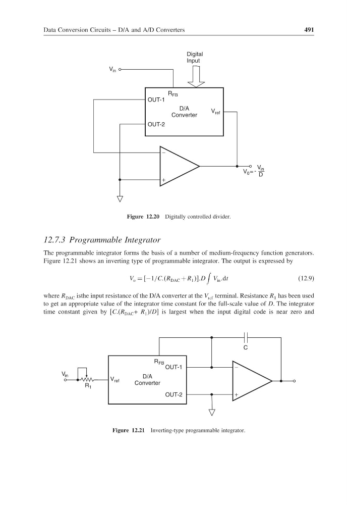
Figure 12.20 Digitally controlled divider.
12.7.3 Programmable Integrator
The programmable integrator forms the basis of a number of medium-frequency function generators.
Figure 12.21 shows an inverting type of programmable integrator. The output is expressed by
V o = −1/CCCR DAC + R 1 D
V in dt
(12.9)
where R DAC isthe input resistance of the D/A converter at the V ref terminal. Resistance R 1 has been used
to get an appropriate value of the integrator time constant for the full-scale value of D. The integrator
time constant given by [CC(R DAC + R 1 /D] is largest when the input digital code is near zero and
−
+
OUT-1
D/A
Converter
R FB
V ref
OUT-2
V in
R 1
C
Figure 12.21 Inverting-type programmable integrator.
491
−
+
OUT-1
D/A
Converter
R FB
Digital
Input
V ref
OUT-2
V in
V 0 = -
V in
D
Figure 12.20 Digitally controlled divider.
12.7.3 Programmable Integrator
The programmable integrator forms the basis of a number of medium-frequency function generators.
Figure 12.21 shows an inverting type of programmable integrator. The output is expressed by
V o = −1/CCCR DAC + R 1 D
V in dt
(12.9)
where R DAC isthe input resistance of the D/A converter at the V ref terminal. Resistance R 1 has been used
to get an appropriate value of the integrator time constant for the full-scale value of D. The integrator
time constant given by [CC(R DAC + R 1 /D] is largest when the input digital code is near zero and
−
+
OUT-1
D/A
Converter
R FB
V ref
OUT-2
V in
R 1
C
Figure 12.21 Inverting-type programmable integrator.