

490
Digital Electronics
12.7 D/A Converter Applications
In addition to being an integral part of some of the architectures of popular varieties of A/D
converters, D/A converters are extensively used in a variety of other application circuits. Some common
applications include multipliers, digitally controlled dividers, programmable integrators, low-frequency
function generators and digitally controlled filters.
12.7.1 D/A Converter as a Multiplier
The basic D/A converter operated in the current steering mode with the output opamp wired as a
current-to-voltage converter works as a multiplier where the output voltage is the product of the
analogue input applied at the V ref terminal and the digital word input. CMOS D/A converters are
much better suited to multiplying applications as the multiplying capabilities of other types of D/A
converter are restricted to a limited range of input voltage. One such application circuit where the
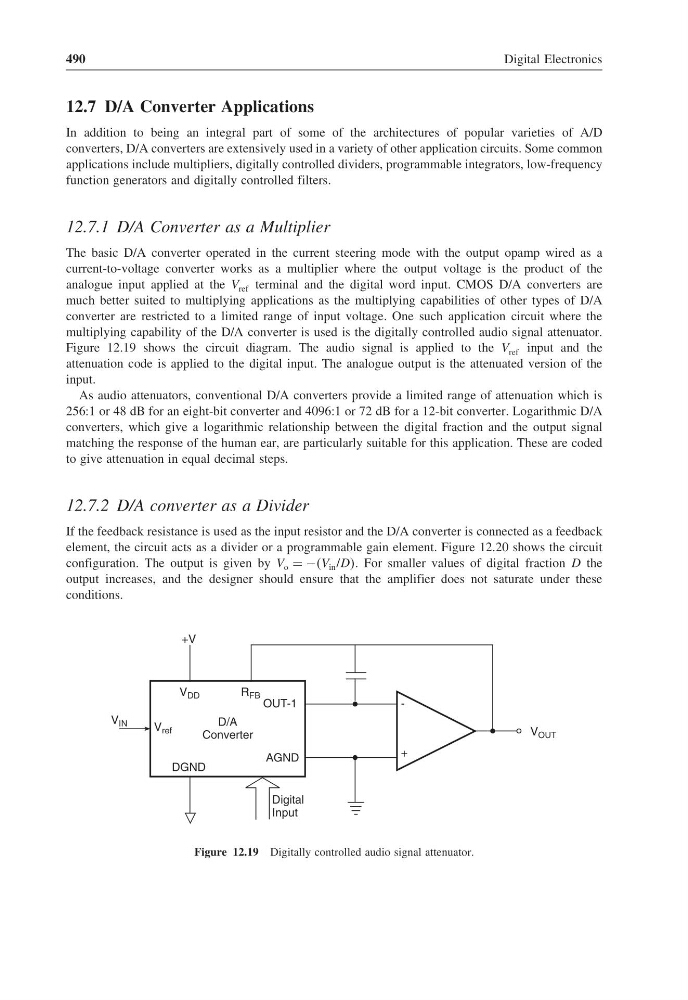
multiplying capability of the D/A converter is used is the digitally controlled audio signal attenuator.
Figure 12.19 shows the circuit diagram. The audio signal is applied to the V ref input and the
attenuation code is applied to the digital input. The analogue output is the attenuated version of the
input.
As audio attenuators, conventional D/A converters provide a limited range of attenuation which is
256:1 or 48 dB for an eight-bit converter and 4096:1 or 72 dB for a 12-bit converter. Logarithmic D/A
converters, which give a logarithmic relationship between the digital fraction and the output signal
matching the response of the human ear, are particularly suitable for this application. These are coded
to give attenuation in equal decimal steps.
12.7.2 D/A converter as a Divider
If the feedback resistance is used as the input resistor and the D/A converter is connected as a feedback
element, the circuit acts as a divider or a programmable gain element. Figure 12.20 shows the circuit
configuration. The output is given by V o = −V in /DDD For smaller values of digital fraction D the
output increases, and the designer should ensure that the amplifier does not saturate under these
conditions.
-
+
OUT-1
AGND
D/A
Converter
R FB
V DD
DGND
+V
Digital
Input
V ref
V OUT
V IN
Figure 12.19 Digitally controlled audio signal attenuator.
Digital Electronics
12.7 D/A Converter Applications
In addition to being an integral part of some of the architectures of popular varieties of A/D
converters, D/A converters are extensively used in a variety of other application circuits. Some common
applications include multipliers, digitally controlled dividers, programmable integrators, low-frequency
function generators and digitally controlled filters.
12.7.1 D/A Converter as a Multiplier
The basic D/A converter operated in the current steering mode with the output opamp wired as a
current-to-voltage converter works as a multiplier where the output voltage is the product of the
analogue input applied at the V ref terminal and the digital word input. CMOS D/A converters are
much better suited to multiplying applications as the multiplying capabilities of other types of D/A
converter are restricted to a limited range of input voltage. One such application circuit where the
multiplying capability of the D/A converter is used is the digitally controlled audio signal attenuator.
Figure 12.19 shows the circuit diagram. The audio signal is applied to the V ref input and the
attenuation code is applied to the digital input. The analogue output is the attenuated version of the
input.
As audio attenuators, conventional D/A converters provide a limited range of attenuation which is
256:1 or 48 dB for an eight-bit converter and 4096:1 or 72 dB for a 12-bit converter. Logarithmic D/A
converters, which give a logarithmic relationship between the digital fraction and the output signal
matching the response of the human ear, are particularly suitable for this application. These are coded
to give attenuation in equal decimal steps.
12.7.2 D/A converter as a Divider
If the feedback resistance is used as the input resistor and the D/A converter is connected as a feedback
element, the circuit acts as a divider or a programmable gain element. Figure 12.20 shows the circuit
configuration. The output is given by V o = −V in /DDD For smaller values of digital fraction D the
output increases, and the designer should ensure that the amplifier does not saturate under these
conditions.
-
+
OUT-1
AGND
D/A
Converter
R FB
V DD
DGND
+V
Digital
Input
V ref
V OUT
V IN
Figure 12.19 Digitally controlled audio signal attenuator.