

Data Conversion Circuits – D/A and A/D Converters
485
4-Bit
Counter
Q 3
Q 2
Q 1
Q 0
(MSB)
Clk
D/A
Converter
Analog O/P
(LSB)
Figure 12.12 Example 12.4.
15
14
13
12
11
10
9
8
7
6
5
4
3
2
1
1 2 3 4 5 6 7 8 9 10 11 12 13 14 15 16
Analog Output (V)
(ms)
t
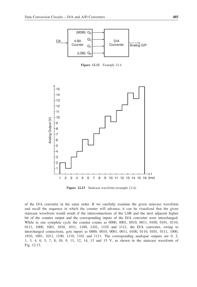
Figure 12.13 Staircase waveform (example 12.4).
of the D/A converter in the same order. If we carefully examine the given staircase waveform
and recall the sequence in which the counter will advance, it can be visualized that the given
staircase waveform would result if the interconnections of the LSB and the next adjacent higher
bit of the counter output and the corresponding inputs of the D/A converter were interchanged.
While in one complete cycle the counter counts as 0000, 0001, 0010, 0011, 0100, 0101, 0110,
0111, 1000, 1001, 1010, 1011, 1100, 1101, 1110 and 1111, the D/A converter, owing to
interchanged connections, gets inputs as 0000, 0010, 0001, 0011, 0100, 0110, 0101, 0111, 1000,
1010, 1001, 1011, 1100, 1110, 1101 and 1111. The corresponding analogue outputs are 0, 2,
1, 3, 4, 6, 5, 7, 8, 10, 9, 11, 12, 14, 13 and 15 V, as shown in the staircase waveform of
Fig. 12.13.
485
4-Bit
Counter
Q 3
Q 2
Q 1
Q 0
(MSB)
Clk
D/A
Converter
Analog O/P
(LSB)
Figure 12.12 Example 12.4.
15
14
13
12
11
10
9
8
7
6
5
4
3
2
1
1 2 3 4 5 6 7 8 9 10 11 12 13 14 15 16
Analog Output (V)
(ms)
t
Figure 12.13 Staircase waveform (example 12.4).
of the D/A converter in the same order. If we carefully examine the given staircase waveform
and recall the sequence in which the counter will advance, it can be visualized that the given
staircase waveform would result if the interconnections of the LSB and the next adjacent higher
bit of the counter output and the corresponding inputs of the D/A converter were interchanged.
While in one complete cycle the counter counts as 0000, 0001, 0010, 0011, 0100, 0101, 0110,
0111, 1000, 1001, 1010, 1011, 1100, 1101, 1110 and 1111, the D/A converter, owing to
interchanged connections, gets inputs as 0000, 0010, 0001, 0011, 0100, 0110, 0101, 0111, 1000,
1010, 1001, 1011, 1100, 1110, 1101 and 1111. The corresponding analogue outputs are 0, 2,
1, 3, 4, 6, 5, 7, 8, 10, 9, 11, 12, 14, 13 and 15 V, as shown in the staircase waveform of
Fig. 12.13.