

484
Digital Electronics
D/A
Converter
{
D 2
C 2
B 2
A 2
D 1
C 1
B 1
A 1
O/P
MSD
{
D 0
C 0
B 0
A 0
LSD
MSB
LSB
MSB
LSB
MSB
LSB
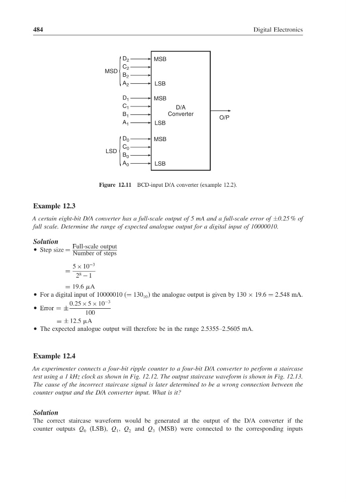
Figure 12.11 BCD-input D/A converter (example 12.2).
Example 12.3
A certain eight-bit D/A converter has a full-scale output of 5 mA and a full-scale error of ±0.25 % of
full scale. Determine the range of expected analogue output for a digital input of 10000010.
Solution
• Step size =
Full-scale output
Number of steps
=
5 × 10
−3
2 8 − 1
= 19.6 A
• For a digital input of 10000010 (= 130 10 the analogue output is given by 130 × 19.6 = 2.548 mA.
• Error = ±
025 × 5 × 10
−3
100
= ± 12.5 A
• The expected analogue output will therefore be in the range 2.5355–2.5605 mA.
Example 12.4
An experimenter connects a four-bit ripple counter to a four-bit D/A converter to perform a staircase
test using a 1 kHz clock as shown in Fig. 12.12. The output staircase waveform is shown in Fig. 12.13.
The cause of the incorrect staircase signal is later determined to be a wrong connection between the
counter output and the D/A converter input. What is it?
Solution
The correct staircase waveform would be generated at the output of the D/A converter if the
counter outputs Q 0 (LSB), Q 1 , Q 2 and Q 3 (MSB) were connected to the corresponding inputs
Digital Electronics
D/A
Converter
{
D 2
C 2
B 2
A 2
D 1
C 1
B 1
A 1
O/P
MSD
{
D 0
C 0
B 0
A 0
LSD
MSB
LSB
MSB
LSB
MSB
LSB
Figure 12.11 BCD-input D/A converter (example 12.2).
Example 12.3
A certain eight-bit D/A converter has a full-scale output of 5 mA and a full-scale error of ±0.25 % of
full scale. Determine the range of expected analogue output for a digital input of 10000010.
Solution
• Step size =
Full-scale output
Number of steps
=
5 × 10
−3
2 8 − 1
= 19.6 A
• For a digital input of 10000010 (= 130 10 the analogue output is given by 130 × 19.6 = 2.548 mA.
• Error = ±
025 × 5 × 10
−3
100
= ± 12.5 A
• The expected analogue output will therefore be in the range 2.5355–2.5605 mA.
Example 12.4
An experimenter connects a four-bit ripple counter to a four-bit D/A converter to perform a staircase
test using a 1 kHz clock as shown in Fig. 12.12. The output staircase waveform is shown in Fig. 12.13.
The cause of the incorrect staircase signal is later determined to be a wrong connection between the
counter output and the D/A converter input. What is it?
Solution
The correct staircase waveform would be generated at the output of the D/A converter if the
counter outputs Q 0 (LSB), Q 1 , Q 2 and Q 3 (MSB) were connected to the corresponding inputs