

474
Digital Electronics
how different bits in the digital input data contribute a different quantum to the overall output analogue
voltage or current, and also that the LSB has the least and the MSB the highest weight.
12.1.1 Simple Resistive Divider Network for D/A Conversion
Simple resistive networks can be used to convert a digital input into an equivalent analogue output.
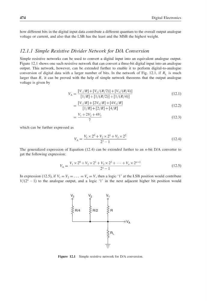
Figure 12.1 shows one such resistive network that can convert a three-bit digital input into an analogue
output. This network, however, can be extended further to enable it to perform digital-to-analogue
conversion of digital data with a larger number of bits. In the network of Fig. 12.1, if R L is much
larger than RR it can be proved with the help of simple network theorems that the output analogue
voltage is given by
V A =
V 1 /RR + V 2 //R/2 + V 3 //R/4
1/RR + 1//R/2 + 1//R/4
(12.1)
=
V 1 /RR + 2V 2 /RR + 4V 3 /RR
1/RR + 2/RR + 4/RR
(12.2)
=
V 1 + 2V 2 + 4V 3
7
(12.3)
which can be further expressed as
V A =
V 1 × 2
0
+ V 2 × 2
1
+ V 3 × 2
2
2 3 − 1
(12.4)
The generalized expression of Equation (12.4) can be extended further to an n-bit D/A converter to
get the following expression:
V A =
V 1 × 2
0
+ V 2 × 2
1
+ V 3 × 2
2
+ · · · + V n × 2
n−1
2 n − 1
(12.5)
In expression (12.5), if V 1 = V 2 = = V n = V , then a logic ‘1’ at the LSB position would contribute
V/(2
n
− 1) to the analogue output, and a logic ‘1’ in the next adjacent higher bit position would
R
V 1
R/2
V 2
R/4
V 3
R L
V A
Figure 12.1 Simple resistive network for D/A conversion.
Digital Electronics
how different bits in the digital input data contribute a different quantum to the overall output analogue
voltage or current, and also that the LSB has the least and the MSB the highest weight.
12.1.1 Simple Resistive Divider Network for D/A Conversion
Simple resistive networks can be used to convert a digital input into an equivalent analogue output.
Figure 12.1 shows one such resistive network that can convert a three-bit digital input into an analogue
output. This network, however, can be extended further to enable it to perform digital-to-analogue
conversion of digital data with a larger number of bits. In the network of Fig. 12.1, if R L is much
larger than RR it can be proved with the help of simple network theorems that the output analogue
voltage is given by
V A =
V 1 /RR + V 2 //R/2 + V 3 //R/4
1/RR + 1//R/2 + 1//R/4
(12.1)
=
V 1 /RR + 2V 2 /RR + 4V 3 /RR
1/RR + 2/RR + 4/RR
(12.2)
=
V 1 + 2V 2 + 4V 3
7
(12.3)
which can be further expressed as
V A =
V 1 × 2
0
+ V 2 × 2
1
+ V 3 × 2
2
2 3 − 1
(12.4)
The generalized expression of Equation (12.4) can be extended further to an n-bit D/A converter to
get the following expression:
V A =
V 1 × 2
0
+ V 2 × 2
1
+ V 3 × 2
2
+ · · · + V n × 2
n−1
2 n − 1
(12.5)
In expression (12.5), if V 1 = V 2 = = V n = V , then a logic ‘1’ at the LSB position would contribute
V/(2
n
− 1) to the analogue output, and a logic ‘1’ in the next adjacent higher bit position would
R
V 1
R/2
V 2
R/4
V 3
R L
V A
Figure 12.1 Simple resistive network for D/A conversion.