

Counters and Registers
423
11.5 Synchronous (or Parallel) Counters
Ripple counters discussed thus far in this chapter are asynchronous in nature as the different flipflops comprising the counter are not clocked simultaneously and in synchronism with the clock
pulses. The total propagation delay in such a counter, as explained earlier, is equal to the sum of
propagation delays due to different flip-flops. The propagation delay becomes prohibitively large in
a ripple counter with a large count. On the other hand, in a synchronous counter, all flip-flops in the
counter are clocked simultaneously in synchronism with the clock, and as a consequence all flip-flops
change state at the same time. The propagation delay in this case is independent of the number of
flip-flops used.
Since the different flip-flops in a synchronous counter are clocked at the same time, there needs to
be additional logic circuitry to ensure that the various flip-flops toggle at the right time. For instance,
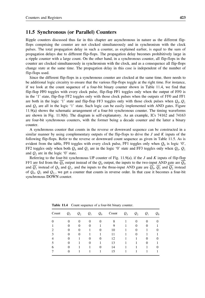
if we look at the count sequence of a four-bit binary counter shown in Table 11.4, we find that
flip-flop FF0 toggles with every clock pulse, flip-flop FF1 toggles only when the output of FF0 is
in the ‘1’ state, flip-flop FF2 toggles only with those clock pulses when the outputs of FF0 and FF1
are both in the logic ‘1’ state and flip-flop FF3 toggles only with those clock pulses when Q 0 Q 1
and Q 2 are all in the logic ‘1’ state. Such logic can be easily implemented with AND gates. Figure
11.9(a) shows the schematic arrangement of a four-bit synchronous counter. The timing waveforms
are shown in Fig. 11.9(b). The diagram is self-explanatory. As an example, ICs 74162 and 74163
are four-bit synchronous counters, with the former being a decade counter and the latter a binary
counter.
A synchronous counter that counts in the reverse or downward sequence can be constructed in a
similar manner by using complementary outputs of the flip-flops to drive the J and K inputs of the
following flip-flops. Refer to the reverse or downward count sequence as given in Table 11.5. As is
evident from the table, FF0 toggles with every clock pulse, FF1 toggles only when Q 0 is logic ‘0’,
FF2 toggles only when both Q 0 and Q 1 are in the logic ‘0’ state and FF3 toggles only when Q 0 , Q 1
and Q 2 are in the logic ‘0’ state.
Referring to the four-bit synchronous UP counter of Fig. 11.9(a), if the J and K inputs of flip-flop
FF1 are fed from the Q 0 output instead of the Q 0 output, the inputs to the two-input AND gate are Q 0
and Q 1 instead of Q 0 and Q 1 , and the inputs to the three-input AND gate are Q 0 , Q 1 and Q 2 instead
of Q 0 , Q 1 and Q 2 , we get a counter that counts in reverse order. In that case it becomes a four-bit
synchronous DOWN counter.
Table 11.4 Count sequence of a four-bit binary counter.
Count
Q 3
Q 2
Q 1
Q 0
Count
Q 3
Q 2
Q 1
Q 0
0
0
0
0
0
8
1
0
0
0
1
0
0
0
1
9
1
0
0
1
2
0
0
1
0
1 0
1
0
1
0
3
0
0
1
1
1 1
1
0
1
1
4
0
1
0
0
1 2
1
1
0
0
5
0
1
0
1
1 3
1
1
0
1
6
0
1
1
0
1 4
1
1
1
0
7
0
1
1
1
1 5
1
1
1
1
423
11.5 Synchronous (or Parallel) Counters
Ripple counters discussed thus far in this chapter are asynchronous in nature as the different flipflops comprising the counter are not clocked simultaneously and in synchronism with the clock
pulses. The total propagation delay in such a counter, as explained earlier, is equal to the sum of
propagation delays due to different flip-flops. The propagation delay becomes prohibitively large in
a ripple counter with a large count. On the other hand, in a synchronous counter, all flip-flops in the
counter are clocked simultaneously in synchronism with the clock, and as a consequence all flip-flops
change state at the same time. The propagation delay in this case is independent of the number of
flip-flops used.
Since the different flip-flops in a synchronous counter are clocked at the same time, there needs to
be additional logic circuitry to ensure that the various flip-flops toggle at the right time. For instance,
if we look at the count sequence of a four-bit binary counter shown in Table 11.4, we find that
flip-flop FF0 toggles with every clock pulse, flip-flop FF1 toggles only when the output of FF0 is
in the ‘1’ state, flip-flop FF2 toggles only with those clock pulses when the outputs of FF0 and FF1
are both in the logic ‘1’ state and flip-flop FF3 toggles only with those clock pulses when Q 0 Q 1
and Q 2 are all in the logic ‘1’ state. Such logic can be easily implemented with AND gates. Figure
11.9(a) shows the schematic arrangement of a four-bit synchronous counter. The timing waveforms
are shown in Fig. 11.9(b). The diagram is self-explanatory. As an example, ICs 74162 and 74163
are four-bit synchronous counters, with the former being a decade counter and the latter a binary
counter.
A synchronous counter that counts in the reverse or downward sequence can be constructed in a
similar manner by using complementary outputs of the flip-flops to drive the J and K inputs of the
following flip-flops. Refer to the reverse or downward count sequence as given in Table 11.5. As is
evident from the table, FF0 toggles with every clock pulse, FF1 toggles only when Q 0 is logic ‘0’,
FF2 toggles only when both Q 0 and Q 1 are in the logic ‘0’ state and FF3 toggles only when Q 0 , Q 1
and Q 2 are in the logic ‘0’ state.
Referring to the four-bit synchronous UP counter of Fig. 11.9(a), if the J and K inputs of flip-flop
FF1 are fed from the Q 0 output instead of the Q 0 output, the inputs to the two-input AND gate are Q 0
and Q 1 instead of Q 0 and Q 1 , and the inputs to the three-input AND gate are Q 0 , Q 1 and Q 2 instead
of Q 0 , Q 1 and Q 2 , we get a counter that counts in reverse order. In that case it becomes a four-bit
synchronous DOWN counter.
Table 11.4 Count sequence of a four-bit binary counter.
Count
Q 3
Q 2
Q 1
Q 0
Count
Q 3
Q 2
Q 1
Q 0
0
0
0
0
0
8
1
0
0
0
1
0
0
0
1
9
1
0
0
1
2
0
0
1
0
1 0
1
0
1
0
3
0
0
1
1
1 1
1
0
1
1
4
0
1
0
0
1 2
1
1
0
0
5
0
1
0
1
1 3
1
1
0
1
6
0
1
1
0
1 4
1
1
1
0
7
0
1
1
1
1 5
1
1
1
1