

422
Digital Electronics
Q 0
FF0
J
K
‘1’
Clock
Q 0(LSB)
Clk
Q 1
FF1
J
K
Q 1
Clk
Q 2
FF2
J
K
Q 2
Clk
Q 3
FF3
J
K
Q 3(MSB)
Clk
Q 0
Q 1
Q 2
Q 3
Input
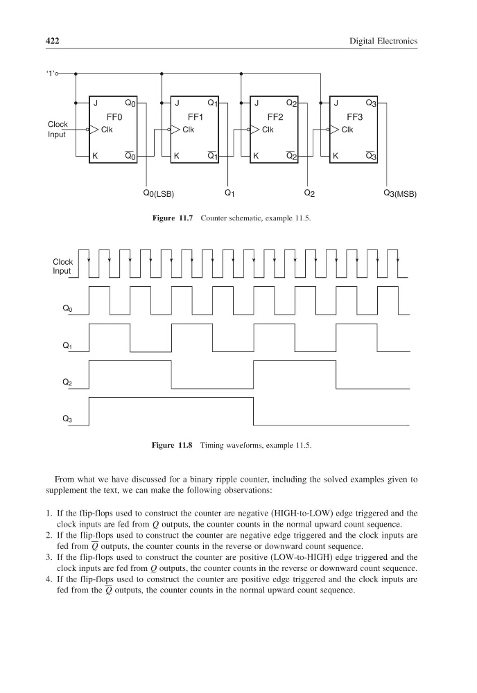
Figure 11.7 Counter schematic, example 11.5.
Clock
Input
Q 0
Q 1
Q 2
Q 3
Figure 11.8 Timing waveforms, example 11.5.
From what we have discussed for a binary ripple counter, including the solved examples given to
supplement the text, we can make the following observations:
1. If the flip-flops used to construct the counter are negative (HIGH-to-LOW) edge triggered and the
clock inputs are fed from Q outputs, the counter counts in the normal upward count sequence.
2. If the flip-flops used to construct the counter are negative edge triggered and the clock inputs are
fed from Q outputs, the counter counts in the reverse or downward count sequence.
3. If the flip-flops used to construct the counter are positive (LOW-to-HIGH) edge triggered and the
clock inputs are fed from Q outputs, the counter counts in the reverse or downward count sequence.
4. If the flip-flops used to construct the counter are positive edge triggered and the clock inputs are
fed from the Q outputs, the counter counts in the normal upward count sequence.
Digital Electronics
Q 0
FF0
J
K
‘1’
Clock
Q 0(LSB)
Clk
Q 1
FF1
J
K
Q 1
Clk
Q 2
FF2
J
K
Q 2
Clk
Q 3
FF3
J
K
Q 3(MSB)
Clk
Q 0
Q 1
Q 2
Q 3
Input
Figure 11.7 Counter schematic, example 11.5.
Clock
Input
Q 0
Q 1
Q 2
Q 3
Figure 11.8 Timing waveforms, example 11.5.
From what we have discussed for a binary ripple counter, including the solved examples given to
supplement the text, we can make the following observations:
1. If the flip-flops used to construct the counter are negative (HIGH-to-LOW) edge triggered and the
clock inputs are fed from Q outputs, the counter counts in the normal upward count sequence.
2. If the flip-flops used to construct the counter are negative edge triggered and the clock inputs are
fed from Q outputs, the counter counts in the reverse or downward count sequence.
3. If the flip-flops used to construct the counter are positive (LOW-to-HIGH) edge triggered and the
clock inputs are fed from Q outputs, the counter counts in the reverse or downward count sequence.
4. If the flip-flops used to construct the counter are positive edge triggered and the clock inputs are
fed from the Q outputs, the counter counts in the normal upward count sequence.