

412
Digital Electronics
Q 1
FF1
J
K
Q 2
FF2
J
K
Q n-1
FF(n-1)
J
K
Q n
FF(n)
J
K
1
Clock
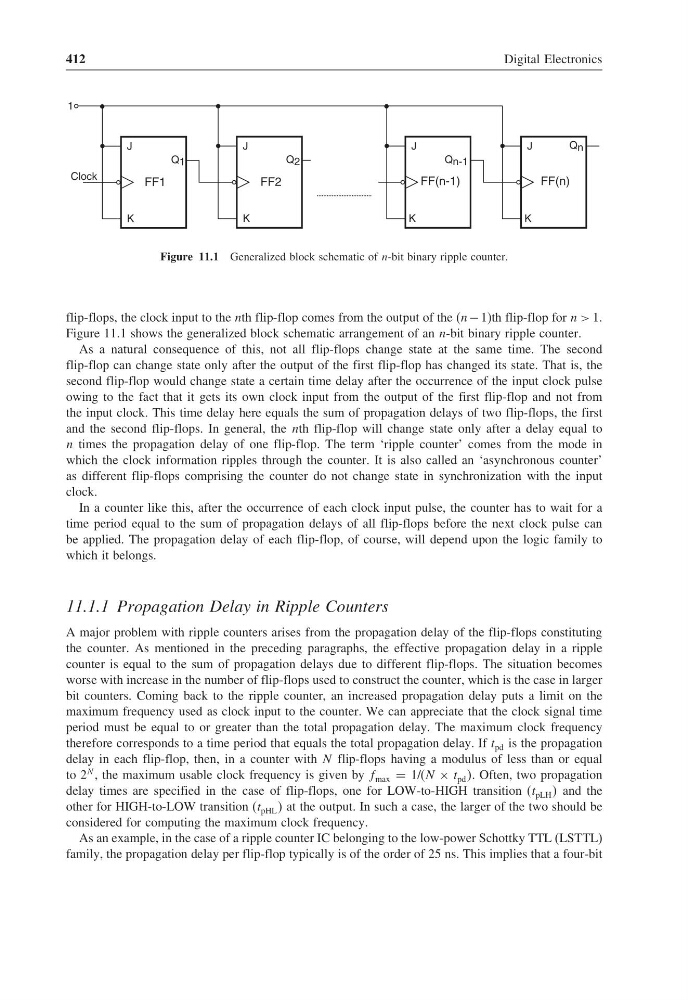
Figure 11.1 Generalized block schematic of n-bit binary ripple counter.
flip-flops, the clock input to the nth flip-flop comes from the output of the (n − 1)th flip-flop for n > 1.
Figure 11.1 shows the generalized block schematic arrangement of an n-bit binary ripple counter.
As a natural consequence of this, not all flip-flops change state at the same time. The second
flip-flop can change state only after the output of the first flip-flop has changed its state. That is, the
second flip-flop would change state a certain time delay after the occurrence of the input clock pulse
owing to the fact that it gets its own clock input from the output of the first flip-flop and not from
the input clock. This time delay here equals the sum of propagation delays of two flip-flops, the first
and the second flip-flops. In general, the nth flip-flop will change state only after a delay equal to
n times the propagation delay of one flip-flop. The term ‘ripple counter’ comes from the mode in
which the clock information ripples through the counter. It is also called an ‘asynchronous counter’
as different flip-flops comprising the counter do not change state in synchronization with the input
clock.
In a counter like this, after the occurrence of each clock input pulse, the counter has to wait for a
time period equal to the sum of propagation delays of all flip-flops before the next clock pulse can
be applied. The propagation delay of each flip-flop, of course, will depend upon the logic family to
which it belongs.
11.1.1 Propagation Delay in Ripple Counters
A major problem with ripple counters arises from the propagation delay of the flip-flops constituting
the counter. As mentioned in the preceding paragraphs, the effective propagation delay in a ripple
counter is equal to the sum of propagation delays due to different flip-flops. The situation becomes
worse with increase in the number of flip-flops used to construct the counter, which is the case in larger
bit counters. Coming back to the ripple counter, an increased propagation delay puts a limit on the
maximum frequency used as clock input to the counter. We can appreciate that the clock signal time
period must be equal to or greater than the total propagation delay. The maximum clock frequency
therefore corresponds to a time period that equals the total propagation delay. If t pd is the propagation
delay in each flip-flop, then, in a counter with N flip-flops having a modulus of less than or equal
to 2
N , the maximum usable clock frequency is given by f max = 1/(N × t pd . Often, two propagation
delay times are specified in the case of flip-flops, one for LOW-to-HIGH transition (t pLH and the
other for HIGH-to-LOW transition (t pHL at the output. In such a case, the larger of the two should be
considered for computing the maximum clock frequency.
As an example, in the case of a ripple counter IC belonging to the low-power Schottky TTL (LSTTL)
family, the propagation delay per flip-flop typically is of the order of 25 ns. This implies that a four-bit
Digital Electronics
Q 1
FF1
J
K
Q 2
FF2
J
K
Q n-1
FF(n-1)
J
K
Q n
FF(n)
J
K
1
Clock
Figure 11.1 Generalized block schematic of n-bit binary ripple counter.
flip-flops, the clock input to the nth flip-flop comes from the output of the (n − 1)th flip-flop for n > 1.
Figure 11.1 shows the generalized block schematic arrangement of an n-bit binary ripple counter.
As a natural consequence of this, not all flip-flops change state at the same time. The second
flip-flop can change state only after the output of the first flip-flop has changed its state. That is, the
second flip-flop would change state a certain time delay after the occurrence of the input clock pulse
owing to the fact that it gets its own clock input from the output of the first flip-flop and not from
the input clock. This time delay here equals the sum of propagation delays of two flip-flops, the first
and the second flip-flops. In general, the nth flip-flop will change state only after a delay equal to
n times the propagation delay of one flip-flop. The term ‘ripple counter’ comes from the mode in
which the clock information ripples through the counter. It is also called an ‘asynchronous counter’
as different flip-flops comprising the counter do not change state in synchronization with the input
clock.
In a counter like this, after the occurrence of each clock input pulse, the counter has to wait for a
time period equal to the sum of propagation delays of all flip-flops before the next clock pulse can
be applied. The propagation delay of each flip-flop, of course, will depend upon the logic family to
which it belongs.
11.1.1 Propagation Delay in Ripple Counters
A major problem with ripple counters arises from the propagation delay of the flip-flops constituting
the counter. As mentioned in the preceding paragraphs, the effective propagation delay in a ripple
counter is equal to the sum of propagation delays due to different flip-flops. The situation becomes
worse with increase in the number of flip-flops used to construct the counter, which is the case in larger
bit counters. Coming back to the ripple counter, an increased propagation delay puts a limit on the
maximum frequency used as clock input to the counter. We can appreciate that the clock signal time
period must be equal to or greater than the total propagation delay. The maximum clock frequency
therefore corresponds to a time period that equals the total propagation delay. If t pd is the propagation
delay in each flip-flop, then, in a counter with N flip-flops having a modulus of less than or equal
to 2
N , the maximum usable clock frequency is given by f max = 1/(N × t pd . Often, two propagation
delay times are specified in the case of flip-flops, one for LOW-to-HIGH transition (t pLH and the
other for HIGH-to-LOW transition (t pHL at the output. In such a case, the larger of the two should be
considered for computing the maximum clock frequency.
As an example, in the case of a ripple counter IC belonging to the low-power Schottky TTL (LSTTL)
family, the propagation delay per flip-flop typically is of the order of 25 ns. This implies that a four-bit