

Flip-Flops and Related Devices
401
t pLH
Q -Output
Clock
t pHL
Q -Output
Clock
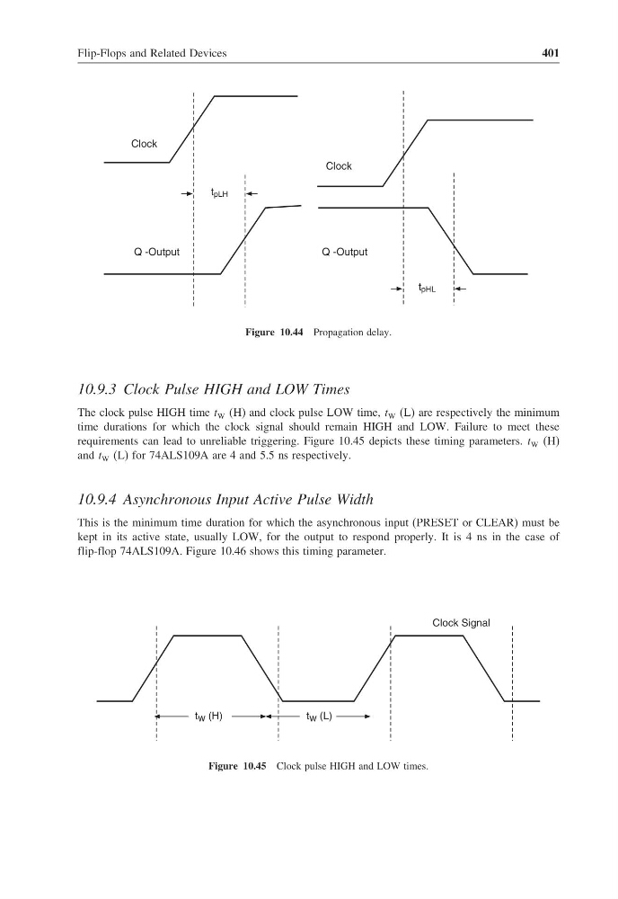
Figure 10.44 Propagation delay.
10.9.3 Clock Pulse HIGH and LOW Times
The clock pulse HIGH time t W (H) and clock pulse LOW time, t W (L) are respectively the minimum
time durations for which the clock signal should remain HIGH and LOW. Failure to meet these
requirements can lead to unreliable triggering. Figure 10.45 depicts these timing parameters. t W (H)
and t W (L) for 74ALS109A are 4 and 5.5 ns respectively.
10.9.4 Asynchronous Input Active Pulse Width
This is the minimum time duration for which the asynchronous input (PRESET or CLEAR) must be
kept in its active state, usually LOW, for the output to respond properly. It is 4 ns in the case of
flip-flop 74ALS109A. Figure 10.46 shows this timing parameter.
t w (H)
t w (L)
Clock Signal
Figure 10.45 Clock pulse HIGH and LOW times.
401
t pLH
Q -Output
Clock
t pHL
Q -Output
Clock
Figure 10.44 Propagation delay.
10.9.3 Clock Pulse HIGH and LOW Times
The clock pulse HIGH time t W (H) and clock pulse LOW time, t W (L) are respectively the minimum
time durations for which the clock signal should remain HIGH and LOW. Failure to meet these
requirements can lead to unreliable triggering. Figure 10.45 depicts these timing parameters. t W (H)
and t W (L) for 74ALS109A are 4 and 5.5 ns respectively.
10.9.4 Asynchronous Input Active Pulse Width
This is the minimum time duration for which the asynchronous input (PRESET or CLEAR) must be
kept in its active state, usually LOW, for the output to respond properly. It is 4 ns in the case of
flip-flop 74ALS109A. Figure 10.46 shows this timing parameter.
t w (H)
t w (L)
Clock Signal
Figure 10.45 Clock pulse HIGH and LOW times.