

390
Digital Electronics
b
d
f
h
l
j
a
c
e
g
k
i
(a)
(b)
n
m
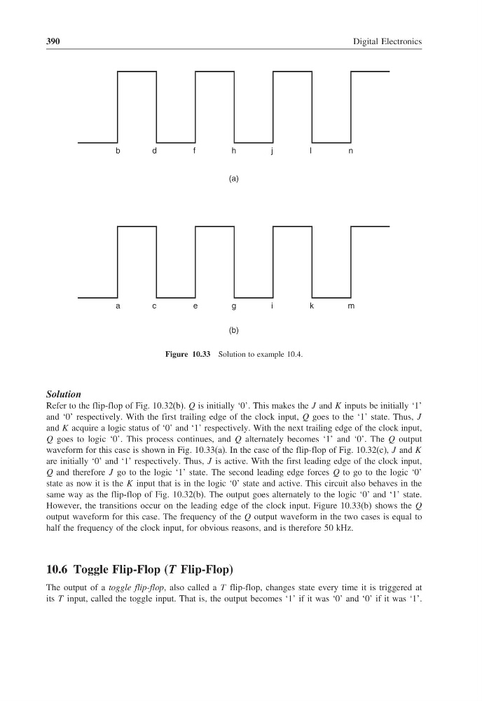
Figure 10.33 Solution to example 10.4.
Solution
Refer to the flip-flop of Fig. 10.32(b). Q is initially ‘0’. This makes the J and K inputs be initially ‘1’
and ‘0’ respectively. With the first trailing edge of the clock input, Q goes to the ‘1’ state. Thus, J
and K acquire a logic status of ‘0’ and ‘1’ respectively. With the next trailing edge of the clock input,
Q goes to logic ‘0’. This process continues, and Q alternately becomes ‘1’ and ‘0’. The Q output
waveform for this case is shown in Fig. 10.33(a). In the case of the flip-flop of Fig. 10.32(c), J and K
are initially ‘0’ and ‘1’ respectively. Thus, J is active. With the first leading edge of the clock input,
Q and therefore J go to the logic ‘1’ state. The second leading edge forces Q to go to the logic ‘0’
state as now it is the K input that is in the logic ‘0’ state and active. This circuit also behaves in the
same way as the flip-flop of Fig. 10.32(b). The output goes alternately to the logic ‘0’ and ‘1’ state.
However, the transitions occur on the leading edge of the clock input. Figure 10.33(b) shows the Q
output waveform for this case. The frequency of the Q output waveform in the two cases is equal to
half the frequency of the clock input, for obvious reasons, and is therefore 50 kHz.
10.6 Toggle Flip-Flop (T Flip-Flop)
The output of a toggle flip-flop, also called a T flip-flop, changes state every time it is triggered at
its T input, called the toggle input. That is, the output becomes ‘1’ if it was ‘0’ and ‘0’ if it was ‘1’.
Digital Electronics
b
d
f
h
l
j
a
c
e
g
k
i
(a)
(b)
n
m
Figure 10.33 Solution to example 10.4.
Solution
Refer to the flip-flop of Fig. 10.32(b). Q is initially ‘0’. This makes the J and K inputs be initially ‘1’
and ‘0’ respectively. With the first trailing edge of the clock input, Q goes to the ‘1’ state. Thus, J
and K acquire a logic status of ‘0’ and ‘1’ respectively. With the next trailing edge of the clock input,
Q goes to logic ‘0’. This process continues, and Q alternately becomes ‘1’ and ‘0’. The Q output
waveform for this case is shown in Fig. 10.33(a). In the case of the flip-flop of Fig. 10.32(c), J and K
are initially ‘0’ and ‘1’ respectively. Thus, J is active. With the first leading edge of the clock input,
Q and therefore J go to the logic ‘1’ state. The second leading edge forces Q to go to the logic ‘0’
state as now it is the K input that is in the logic ‘0’ state and active. This circuit also behaves in the
same way as the flip-flop of Fig. 10.32(b). The output goes alternately to the logic ‘0’ and ‘1’ state.
However, the transitions occur on the leading edge of the clock input. Figure 10.33(b) shows the Q
output waveform for this case. The frequency of the Q output waveform in the two cases is equal to
half the frequency of the clock input, for obvious reasons, and is therefore 50 kHz.
10.6 Toggle Flip-Flop (T Flip-Flop)
The output of a toggle flip-flop, also called a T flip-flop, changes state every time it is triggered at
its T input, called the toggle input. That is, the output becomes ‘1’ if it was ‘0’ and ‘0’ if it was ‘1’.