

Flip-Flops and Related Devices
389
and active LOW J and K inputs. Figure 10.31(b) shows the circuit symbol of the flip-flop represented
by this truth table.
Example 10.4
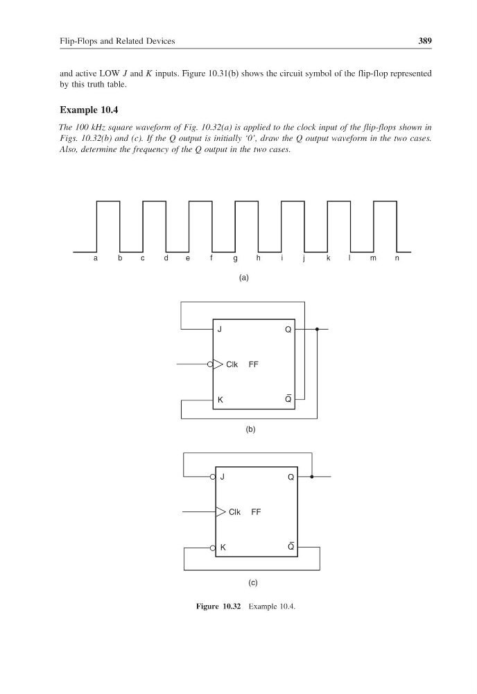
The 100 kHz square waveform of Fig. 10.32(a) is applied to the clock input of the flip-flops shown in
Figs. 10.32(b) and (c). If the Q output is initially ‘0’, draw the Q output waveform in the two cases.
Also, determine the frequency of the Q output in the two cases.
a
b
c
d
e
f
g
h
i
j
k
l
m
n
(a)
Q
Q
–
K
J
Clk FF
(b)
Q
Q
–
K
J
Clk FF
(c)
Figure 10.32 Example 10.4.
389
and active LOW J and K inputs. Figure 10.31(b) shows the circuit symbol of the flip-flop represented
by this truth table.
Example 10.4
The 100 kHz square waveform of Fig. 10.32(a) is applied to the clock input of the flip-flops shown in
Figs. 10.32(b) and (c). If the Q output is initially ‘0’, draw the Q output waveform in the two cases.
Also, determine the frequency of the Q output in the two cases.
a
b
c
d
e
f
g
h
i
j
k
l
m
n
(a)
Q
Q
–
K
J
Clk FF
(b)
Q
Q
–
K
J
Clk FF
(c)
Figure 10.32 Example 10.4.