

384
Digital Electronics
FF
Q
—
Q
S
R
Clk
FF
Q
—
Q
S
R
Clk
(a)
(b)
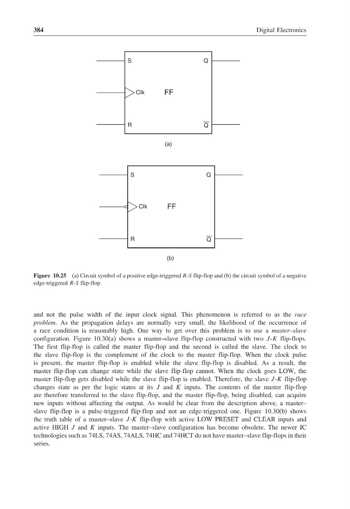
Figure 10.25 (a) Circuit symbol of a positive edge-triggered R-S flip-flop and (b) the circuit symbol of a negative
edge-triggered R-S flip-flop.
and not the pulse width of the input clock signal. This phenomenon is referred to as the race
problem. As the propagation delays are normally very small, the likelihood of the occurrence of
a race condition is reasonably high. One way to get over this problem is to use a master–slave
configuration. Figure 10.30(a) shows a master–slave flip-flop constructed with two J -K flip-flops.
The first flip-flop is called the master flip-flop and the second is called the slave. The clock to
the slave flip-flop is the complement of the clock to the master flip-flop. When the clock pulse
is present, the master flip-flop is enabled while the slave flip-flop is disabled. As a result, the
master flip-flop can change state while the slave flip-flop cannot. When the clock goes LOW, the
master flip-flop gets disabled while the slave flip-flop is enabled. Therefore, the slave J -K flip-flop
changes state as per the logic states at its J and K inputs. The contents of the master flip-flop
are therefore transferred to the slave flip-flop, and the master flip-flop, being disabled, can acquire
new inputs without affecting the output. As would be clear from the description above, a master–
slave flip-flop is a pulse-triggered flip-flop and not an edge-triggered one. Figure 10.30(b) shows
the truth table of a master–slave J -K flip-flop with active LOW PRESET and CLEAR inputs and
active HIGH J and K inputs. The master–slave configuration has become obsolete. The newer IC
technologies such as 74LS, 74AS, 74ALS, 74HC and 74HCT do not have master–slave flip-flops in their
series.
Digital Electronics
FF
Q
—
Q
S
R
Clk
FF
Q
—
Q
S
R
Clk
(a)
(b)
Figure 10.25 (a) Circuit symbol of a positive edge-triggered R-S flip-flop and (b) the circuit symbol of a negative
edge-triggered R-S flip-flop.
and not the pulse width of the input clock signal. This phenomenon is referred to as the race
problem. As the propagation delays are normally very small, the likelihood of the occurrence of
a race condition is reasonably high. One way to get over this problem is to use a master–slave
configuration. Figure 10.30(a) shows a master–slave flip-flop constructed with two J -K flip-flops.
The first flip-flop is called the master flip-flop and the second is called the slave. The clock to
the slave flip-flop is the complement of the clock to the master flip-flop. When the clock pulse
is present, the master flip-flop is enabled while the slave flip-flop is disabled. As a result, the
master flip-flop can change state while the slave flip-flop cannot. When the clock goes LOW, the
master flip-flop gets disabled while the slave flip-flop is enabled. Therefore, the slave J -K flip-flop
changes state as per the logic states at its J and K inputs. The contents of the master flip-flop
are therefore transferred to the slave flip-flop, and the master flip-flop, being disabled, can acquire
new inputs without affecting the output. As would be clear from the description above, a master–
slave flip-flop is a pulse-triggered flip-flop and not an edge-triggered one. Figure 10.30(b) shows
the truth table of a master–slave J -K flip-flop with active LOW PRESET and CLEAR inputs and
active HIGH J and K inputs. The master–slave configuration has become obsolete. The newer IC
technologies such as 74LS, 74AS, 74ALS, 74HC and 74HCT do not have master–slave flip-flops in their
series.