

362
Digital Electronics
Trigger Pulses
Output Pulse
T t
T
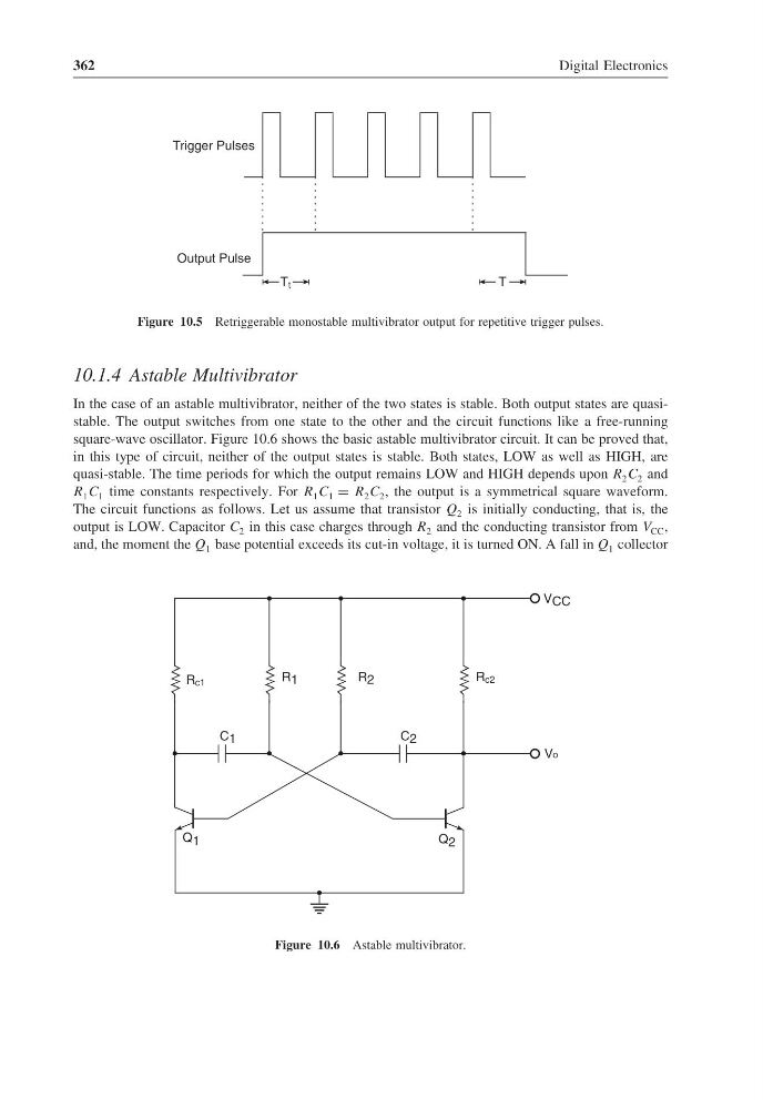
Figure 10.5 Retriggerable monostable multivibrator output for repetitive trigger pulses.
10.1.4 Astable Multivibrator
In the case of an astable multivibrator, neither of the two states is stable. Both output states are quasistable. The output switches from one state to the other and the circuit functions like a free-running
square-wave oscillator. Figure 10.6 shows the basic astable multivibrator circuit. It can be proved that,
in this type of circuit, neither of the output states is stable. Both states, LOW as well as HIGH, are
quasi-stable. The time periods for which the output remains LOW and HIGH depends upon R 2 C 2 and
R 1 C 1 time constants respectively. For R 1 C 1 = R 2 C 2 , the output is a symmetrical square waveform.
The circuit functions as follows. Let us assume that transistor Q 2 is initially conducting, that is, the
output is LOW. Capacitor C 2 in this case charges through R 2 and the conducting transistor from V CC ,
and, the moment the Q 1 base potential exceeds its cut-in voltage, it is turned ON. A fall in Q 1 collector
C 1
C 2
Vo
V CC
R c2
R 2
Q 1
R c1
Q 2
R 1
Figure 10.6 Astable multivibrator.
Digital Electronics
Trigger Pulses
Output Pulse
T t
T
Figure 10.5 Retriggerable monostable multivibrator output for repetitive trigger pulses.
10.1.4 Astable Multivibrator
In the case of an astable multivibrator, neither of the two states is stable. Both output states are quasistable. The output switches from one state to the other and the circuit functions like a free-running
square-wave oscillator. Figure 10.6 shows the basic astable multivibrator circuit. It can be proved that,
in this type of circuit, neither of the output states is stable. Both states, LOW as well as HIGH, are
quasi-stable. The time periods for which the output remains LOW and HIGH depends upon R 2 C 2 and
R 1 C 1 time constants respectively. For R 1 C 1 = R 2 C 2 , the output is a symmetrical square waveform.
The circuit functions as follows. Let us assume that transistor Q 2 is initially conducting, that is, the
output is LOW. Capacitor C 2 in this case charges through R 2 and the conducting transistor from V CC ,
and, the moment the Q 1 base potential exceeds its cut-in voltage, it is turned ON. A fall in Q 1 collector
C 1
C 2
Vo
V CC
R c2
R 2
Q 1
R c1
Q 2
R 1
Figure 10.6 Astable multivibrator.