

Programmable Logic Devices
323
indicate the power level, with ‘L’ and ‘Q’ respectively indicating low and quarter power levels and a
blank representing full power.
Example 9.4
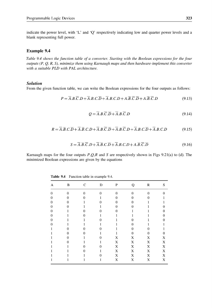
Table 9.4 shows the function table of a converter. Starting with the Boolean expressions for the four
outputs (P, Q, R, S), minimize them using Karnaugh maps and then hardware-implement this converter
with a suitable PLD with PAL architecture.
Solution
From the given function table, we can write the Boolean expressions for the four outputs as follows:
P = AABBCCD + AABBCCD + AABBCCD + AABBCCD + AABBCCD
(9.13)
Q = AABBCCD + AABBCCD
(9.14)
R = AABBCCD + AABBCCD + AABBCCD + AABBCCD + AABBCCD + AABBCCD
(9.15)
S = AABBCCD + AABBCCD + AABBCCD + AABBCCD
(9.16)
Karnaugh maps for the four outputs P,Q,R and S are respectively shown in Figs 9.21(a) to (d). The
minimized Boolean expressions are given by the equations
Table 9.4 Function table in example 9.4.
A
B
C
D
P
Q
R
S
0
0
0
0
0
0
0
0
0
0
0
1
0
0
0
1
0
0
1
0
0
0
1
1
0
0
1
1
0
0
1
0
0
1
0
0
0
1
1
0
0
1
0
1
1
1
1
0
0
1
1
0
1
0
1
0
0
1
1
1
1
0
1
1
1
0
0
0
1
0
0
1
1
0
0
1
1
0
0
0
1
0
1
0
X
X
X
X
1
0
1
1
X
X
X
X
1
1
0
0
X
X
X
X
1
1
0
1
X
X
X
X
1
1
1
0
X
X
X
X
1
1
1
1
X
X
X
X
323
indicate the power level, with ‘L’ and ‘Q’ respectively indicating low and quarter power levels and a
blank representing full power.
Example 9.4
Table 9.4 shows the function table of a converter. Starting with the Boolean expressions for the four
outputs (P, Q, R, S), minimize them using Karnaugh maps and then hardware-implement this converter
with a suitable PLD with PAL architecture.
Solution
From the given function table, we can write the Boolean expressions for the four outputs as follows:
P = AABBCCD + AABBCCD + AABBCCD + AABBCCD + AABBCCD
(9.13)
Q = AABBCCD + AABBCCD
(9.14)
R = AABBCCD + AABBCCD + AABBCCD + AABBCCD + AABBCCD + AABBCCD
(9.15)
S = AABBCCD + AABBCCD + AABBCCD + AABBCCD
(9.16)
Karnaugh maps for the four outputs P,Q,R and S are respectively shown in Figs 9.21(a) to (d). The
minimized Boolean expressions are given by the equations
Table 9.4 Function table in example 9.4.
A
B
C
D
P
Q
R
S
0
0
0
0
0
0
0
0
0
0
0
1
0
0
0
1
0
0
1
0
0
0
1
1
0
0
1
1
0
0
1
0
0
1
0
0
0
1
1
0
0
1
0
1
1
1
1
0
0
1
1
0
1
0
1
0
0
1
1
1
1
0
1
1
1
0
0
0
1
0
0
1
1
0
0
1
1
0
0
0
1
0
1
0
X
X
X
X
1
0
1
1
X
X
X
X
1
1
0
0
X
X
X
X
1
1
0
1
X
X
X
X
1
1
1
0
X
X
X
X
1
1
1
1
X
X
X
X