

Programmable Logic Devices
311
C
B
A
F 1
F 2
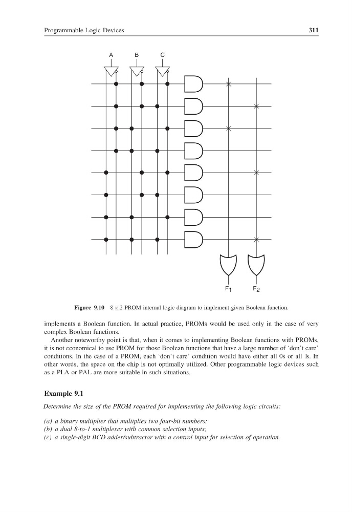
Figure 9.10 8 × 2 PROM internal logic diagram to implement given Boolean function.
implements a Boolean function. In actual practice, PROMs would be used only in the case of very
complex Boolean functions.
Another noteworthy point is that, when it comes to implementing Boolean functions with PROMs,
it is not economical to use PROM for those Boolean functions that have a large number of ‘don’t care’
conditions. In the case of a PROM, each ‘don’t care’ condition would have either all 0s or all 1s. In
other words, the space on the chip is not optimally utilized. Other programmable logic devices such
as a PLA or PAL are more suitable in such situations.
Example 9.1
Determine the size of the PROM required for implementing the following logic circuits:
(a) a binary multiplier that multiplies two four-bit numbers;
(b) a dual 8-to-1 multiplexer with common selection inputs;
(c) a single-digit BCD adder/subtractor with a control input for selection of operation.
311
C
B
A
F 1
F 2
Figure 9.10 8 × 2 PROM internal logic diagram to implement given Boolean function.
implements a Boolean function. In actual practice, PROMs would be used only in the case of very
complex Boolean functions.
Another noteworthy point is that, when it comes to implementing Boolean functions with PROMs,
it is not economical to use PROM for those Boolean functions that have a large number of ‘don’t care’
conditions. In the case of a PROM, each ‘don’t care’ condition would have either all 0s or all 1s. In
other words, the space on the chip is not optimally utilized. Other programmable logic devices such
as a PLA or PAL are more suitable in such situations.
Example 9.1
Determine the size of the PROM required for implementing the following logic circuits:
(a) a binary multiplier that multiplies two four-bit numbers;
(b) a dual 8-to-1 multiplexer with common selection inputs;
(c) a single-digit BCD adder/subtractor with a control input for selection of operation.