

290
Digital Electronics
3-to-8
Decoder
2
2
2
1
2
0
F
0
1
2
3
4
5
6
7
C
A
B
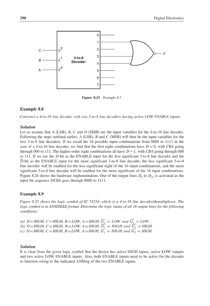
Figure 8.23 Example 8.7.
Example 8.8
Construct a 4-to-16 line decoder with two 3-to-8 line decoders having active LOW ENABLE inputs.
Solution
Let us assume that A (LSB), B, C and D (MSB) are the input variables for the 4-to-16 line decoder.
Following the steps outlined earlier, A (LSB), B and C (MSB) will then be the input variables for the
two 3-to-8 line decoders. If we recall the 16 possible input combinations from 0000 to 1111 in the
case of a 4-to-16 line decoder, we find that the first eight combinations have D = 0, with CBA going
through 000 to 111. The higher-order eight combinations all have D = 1, with CBA going through 000
to 111. If we use the D-bit as the ENABLE input for the less significant 3-to-8 line decoder and the
D-bit as the ENABLE input for the more significant 3-to-8 line decoder, the less significant 3-to-8
line decoder will be enabled for the less significant eight of the 16 input combinations, and the more
significant 3-to-8 line decoder will be enabled for the more significant of the 16 input combinations.
Figure 8.24 shows the hardware implementation. One of the output lines D 0 to D 15 is activated as the
input bit sequence DCBA goes through 0000 to 1111.
Example 8.9
Figure 8.25 shows the logic symbol of IC 74154, which is a 4-to-16 line decoder/demultiplexer. The
logic symbol is in ANSI/IEEE format. Determine the logic status of all 16 output lines for the following
conditions:
(a) D = HIGH, C = HIGH, B = LOW, A = HIGH, G 1 = LOW and G 2 = LOW.
(b) D = HIGH, C = HIGH, B = LOW, A = HIGH, G 1 = HIGH and G 2 = HIGH.
(c) D = HIGH, C = HIGH, B = LOW, A = HIGH, G 1 = HIGH and G 2 = HIGH.
Solution
It is clear from the given logic symbol that the device has active HIGH inputs, active LOW outputs
and two active LOW ENABLE inputs. Also, both ENABLE inputs need to be active for the decoder
to function owing to the indicated ANDing of the two ENABLE inputs.
Digital Electronics
3-to-8
Decoder
2
2
2
1
2
0
F
0
1
2
3
4
5
6
7
C
A
B
Figure 8.23 Example 8.7.
Example 8.8
Construct a 4-to-16 line decoder with two 3-to-8 line decoders having active LOW ENABLE inputs.
Solution
Let us assume that A (LSB), B, C and D (MSB) are the input variables for the 4-to-16 line decoder.
Following the steps outlined earlier, A (LSB), B and C (MSB) will then be the input variables for the
two 3-to-8 line decoders. If we recall the 16 possible input combinations from 0000 to 1111 in the
case of a 4-to-16 line decoder, we find that the first eight combinations have D = 0, with CBA going
through 000 to 111. The higher-order eight combinations all have D = 1, with CBA going through 000
to 111. If we use the D-bit as the ENABLE input for the less significant 3-to-8 line decoder and the
D-bit as the ENABLE input for the more significant 3-to-8 line decoder, the less significant 3-to-8
line decoder will be enabled for the less significant eight of the 16 input combinations, and the more
significant 3-to-8 line decoder will be enabled for the more significant of the 16 input combinations.
Figure 8.24 shows the hardware implementation. One of the output lines D 0 to D 15 is activated as the
input bit sequence DCBA goes through 0000 to 1111.
Example 8.9
Figure 8.25 shows the logic symbol of IC 74154, which is a 4-to-16 line decoder/demultiplexer. The
logic symbol is in ANSI/IEEE format. Determine the logic status of all 16 output lines for the following
conditions:
(a) D = HIGH, C = HIGH, B = LOW, A = HIGH, G 1 = LOW and G 2 = LOW.
(b) D = HIGH, C = HIGH, B = LOW, A = HIGH, G 1 = HIGH and G 2 = HIGH.
(c) D = HIGH, C = HIGH, B = LOW, A = HIGH, G 1 = HIGH and G 2 = HIGH.
Solution
It is clear from the given logic symbol that the device has active HIGH inputs, active LOW outputs
and two active LOW ENABLE inputs. Also, both ENABLE inputs need to be active for the decoder
to function owing to the indicated ANDing of the two ENABLE inputs.