

Multiplexers and Demultiplexers
281
8-to-1
MUX
I 0
I 1
I 7
D 0
D 1
D 2
D 3
D 4
D 5
D 6
D 7
S 0
S 1
S 2
8-to-1
MUX
I 0
I 1
I 7
D 8
D 9
D 10
D 11
D 12
D 13
D 14
D 15
S 0
S 1
S 2
E
E
S 3
S 2
S 1
S 0
Y
Y
F
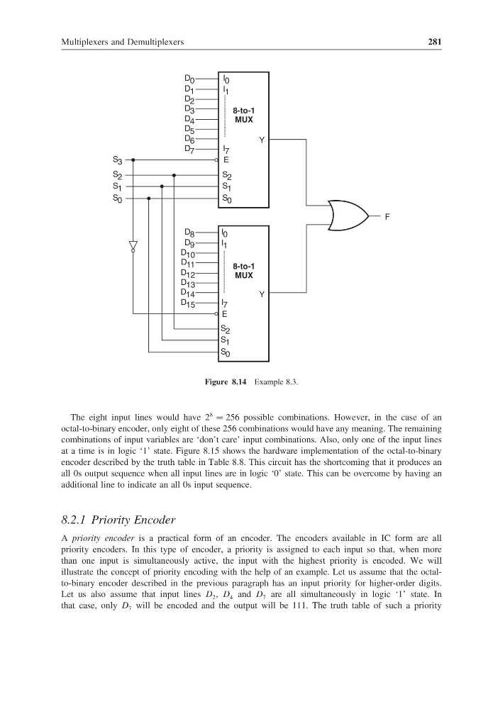
Figure 8.14 Example 8.3.
The eight input lines would have 2
8
= 256 possible combinations. However, in the case of an
octal-to-binary encoder, only eight of these 256 combinations would have any meaning. The remaining
combinations of input variables are ‘don’t care’ input combinations. Also, only one of the input lines
at a time is in logic ‘1’ state. Figure 8.15 shows the hardware implementation of the octal-to-binary
encoder described by the truth table in Table 8.8. This circuit has the shortcoming that it produces an
all 0s output sequence when all input lines are in logic ‘0’ state. This can be overcome by having an
additional line to indicate an all 0s input sequence.
8.2.1 Priority Encoder
A priority encoder is a practical form of an encoder. The encoders available in IC form are all
priority encoders. In this type of encoder, a priority is assigned to each input so that, when more
than one input is simultaneously active, the input with the highest priority is encoded. We will
illustrate the concept of priority encoding with the help of an example. Let us assume that the octalto-binary encoder described in the previous paragraph has an input priority for higher-order digits.
Let us also assume that input lines D 2 , D 4 and D 7 are all simultaneously in logic ‘1’ state. In
that case, only D 7 will be encoded and the output will be 111. The truth table of such a priority
281
8-to-1
MUX
I 0
I 1
I 7
D 0
D 1
D 2
D 3
D 4
D 5
D 6
D 7
S 0
S 1
S 2
8-to-1
MUX
I 0
I 1
I 7
D 8
D 9
D 10
D 11
D 12
D 13
D 14
D 15
S 0
S 1
S 2
E
E
S 3
S 2
S 1
S 0
Y
Y
F
Figure 8.14 Example 8.3.
The eight input lines would have 2
8
= 256 possible combinations. However, in the case of an
octal-to-binary encoder, only eight of these 256 combinations would have any meaning. The remaining
combinations of input variables are ‘don’t care’ input combinations. Also, only one of the input lines
at a time is in logic ‘1’ state. Figure 8.15 shows the hardware implementation of the octal-to-binary
encoder described by the truth table in Table 8.8. This circuit has the shortcoming that it produces an
all 0s output sequence when all input lines are in logic ‘0’ state. This can be overcome by having an
additional line to indicate an all 0s input sequence.
8.2.1 Priority Encoder
A priority encoder is a practical form of an encoder. The encoders available in IC form are all
priority encoders. In this type of encoder, a priority is assigned to each input so that, when more
than one input is simultaneously active, the input with the highest priority is encoded. We will
illustrate the concept of priority encoding with the help of an example. Let us assume that the octalto-binary encoder described in the previous paragraph has an input priority for higher-order digits.
Let us also assume that input lines D 2 , D 4 and D 7 are all simultaneously in logic ‘1’ state. In
that case, only D 7 will be encoded and the output will be 111. The truth table of such a priority