

Arithmetic Circuits
267
Problems
1. A, B, B in , D and B out are respectively the minuend, the subtrahend, the BORROW-IN, the
DIFFERENCE output and the BORROW-OUT in the case of a full subtractor. Determine the bit
status of D and B out for the following values of A, B and B in :
(a) A = 0, B = 1, B in = 1
(b) A = 1, B = 1, B in = 0
(c) A = 1, B = 1, B in = 1
(d) A = 0, B = 0, B in = 1
(a) D = 0, B out = 1; (b) D = 0, B out = 0; (c) D = 1, B out = 1; (d) D = 1, B out = 1
2. Determine the number of half and full adder circuit blocks required to construct a 64-bit binary
parallel adder. Also, determine the number and type of additional logic gates needed to transform
this 64-bit adder into a 64-bit adder–subtractor.
For a 64-bit adder: HA=1, FA=63
For a 64-bit adder–subtractor: HA = 1, FA = 63, EX-OR gates = 64
3. If the minuend, subtrahend and BORROW-IN bits are respectively applied to the Augend, Addend
and the CARRY-IN inputs of a full adder, prove that the SUM output of the full adder will produce
the correct DIFFERENCE output.
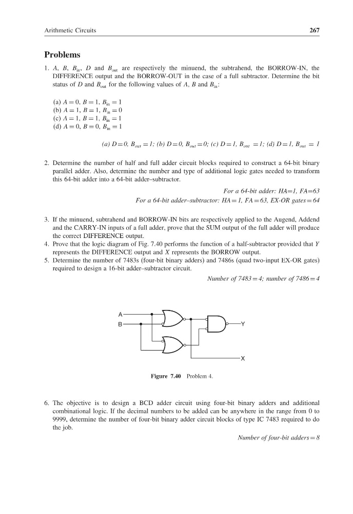
4. Prove that the logic diagram of Fig. 7.40 performs the function of a half-subtractor provided that Y
represents the DIFFERENCE output and X represents the BORROW output.
5. Determine the number of 7483s (four-bit binary adders) and 7486s (quad two-input EX-OR gates)
required to design a 16-bit adder–subtractor circuit.
Number of 7483 = 4; number of 7486 = 4
A
B
Y
X
Figure 7.40 Problem 4.
6. The objective is to design a BCD adder circuit using four-bit binary adders and additional
combinational logic. If the decimal numbers to be added can be anywhere in the range from 0 to
9999, determine the number of four-bit binary adder circuit blocks of type IC 7483 required to do
the job.
Number of four-bit adders = 8
267
Problems
1. A, B, B in , D and B out are respectively the minuend, the subtrahend, the BORROW-IN, the
DIFFERENCE output and the BORROW-OUT in the case of a full subtractor. Determine the bit
status of D and B out for the following values of A, B and B in :
(a) A = 0, B = 1, B in = 1
(b) A = 1, B = 1, B in = 0
(c) A = 1, B = 1, B in = 1
(d) A = 0, B = 0, B in = 1
(a) D = 0, B out = 1; (b) D = 0, B out = 0; (c) D = 1, B out = 1; (d) D = 1, B out = 1
2. Determine the number of half and full adder circuit blocks required to construct a 64-bit binary
parallel adder. Also, determine the number and type of additional logic gates needed to transform
this 64-bit adder into a 64-bit adder–subtractor.
For a 64-bit adder: HA=1, FA=63
For a 64-bit adder–subtractor: HA = 1, FA = 63, EX-OR gates = 64
3. If the minuend, subtrahend and BORROW-IN bits are respectively applied to the Augend, Addend
and the CARRY-IN inputs of a full adder, prove that the SUM output of the full adder will produce
the correct DIFFERENCE output.
4. Prove that the logic diagram of Fig. 7.40 performs the function of a half-subtractor provided that Y
represents the DIFFERENCE output and X represents the BORROW output.
5. Determine the number of 7483s (four-bit binary adders) and 7486s (quad two-input EX-OR gates)
required to design a 16-bit adder–subtractor circuit.
Number of 7483 = 4; number of 7486 = 4
A
B
Y
X
Figure 7.40 Problem 4.
6. The objective is to design a BCD adder circuit using four-bit binary adders and additional
combinational logic. If the decimal numbers to be added can be anywhere in the range from 0 to
9999, determine the number of four-bit binary adder circuit blocks of type IC 7483 required to do
the job.
Number of four-bit adders = 8