

Arithmetic Circuits
261
Binary multipliers are also available in IC form. Some of the popular type numbers in the TTL
family include 74261 which is a 2 × 4 bit multiplier (a four-bit multiplicand designated as B 0 ,B 1 ,B 2 ,
B 3 and B 4 , and a two-bit multiplier designated as M 0 , M 1 and M 2 .
The MSBs B 4 and M 2 are used to represent signs. 74284 and 74285 are 4 × 4 bit multipliers. They
can be used together to perform high-speed multiplication of two four-bit numbers. Figure 7.35 shows
the arrangement. The result of multiplication is often required to be stored in a register. The size of
this register (accumulator) depends upon the number of bits in the result, which at the most can be
equal to the sum of the number of bits in the multiplier and multiplicand. Some multiplier ICs have
an in-built register.
Many microprocessors do not have in their ALU the hardware that can perform multiplication
or other complex arithmetic operations such as division, determining the square root, trigonometric
functions, etc. These operations in these microprocessors are executed through software. For
example, a multiplication operation may be accomplished by using a software program that does
multiplication through repeated execution of addition and shift instructions. Other complex operations
mentioned above can also be executed with similar programs. Although the use of software reduces
the hardware needed in the microprocessor, the computation time in general is higher in the
case of software-executed operations when compared with the use of hardware to perform those
operations.
7.9 Magnitude Comparator
A magnitude comparator is a combinational circuit that compares two given numbers and determines
whether one is equal to, less than or greater than the other. The output is in the form of three binary
variables representing the conditions A = BB A > B and A < B, if A and B are the two numbers being
compared. Depending upon the relative magnitude of the two numbers, the relevant output changes
state. If the two numbers, let us say, are four-bit binary numbers and are designated as (A 3 A 2 A 1 A 0
and (B 3 B 2 B 1 B 0 , the two numbers will be equal if all pairs of significant digits are equal, that is,
A 3 = B 3 , A 2 = B 2 A 1 = B 1 and A 0 = B 0 . In order to determine whether A is greater than or less than
BB we inspect the relative magnitude of pairs of significant digits, starting from the most significant
position. The comparison is done by successively comparing the next adjacent lower pair of digits if
the digits of the pair under examination are equal. The comparison continues until a pair of unequal
digits is reached. In the pair of unequal digits, if A i = 1 and B i = 0, then A > B, and if A i = 0,
B i = 1 then A < B. If X, Y and Z are three variables respectively representing the A = B, A > B
and A < B conditions, then the Boolean expression representing these conditions are given by the
equations
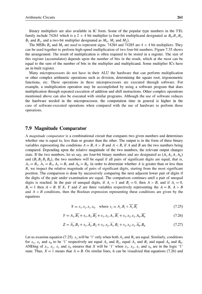
X = x 3 x 2 x 1 x 0 where x i = A i B i + A i B i
(7.25)
Y = A 3 B 3 + x 3 A 2 B 2 + x 3 x 2 A 1 B 1 + x 3 x 2 x 1 A 0 B 0
(7.26)
Z = A 3 B 3 + x 3 A 2 B 2 + x 3 x 2 A 1 B 1 + x 3 x 2 x 1 A 0 B 0
(7.27)
Let us examine equation (7.25). x 3 will be ‘1’ only when both A 3 and B 3 are equal. Similarly, conditions
for x 2 , x 1 and x 0 to be ‘1’ respectively are equal A 2 and B 2 , equal A 1 and B 1 and equal A 0 and B 0 .
ANDing of x 3 , x 2 , x 1 and x 0 ensures that X will be ‘1’ when x 3 , x 2 , x 1 and x 0 are in the logic ‘1’
state. Thus, X = 1 means that A = B. On similar lines, it can be visualized that equations (7.26) and
261
Binary multipliers are also available in IC form. Some of the popular type numbers in the TTL
family include 74261 which is a 2 × 4 bit multiplier (a four-bit multiplicand designated as B 0 ,B 1 ,B 2 ,
B 3 and B 4 , and a two-bit multiplier designated as M 0 , M 1 and M 2 .
The MSBs B 4 and M 2 are used to represent signs. 74284 and 74285 are 4 × 4 bit multipliers. They
can be used together to perform high-speed multiplication of two four-bit numbers. Figure 7.35 shows
the arrangement. The result of multiplication is often required to be stored in a register. The size of
this register (accumulator) depends upon the number of bits in the result, which at the most can be
equal to the sum of the number of bits in the multiplier and multiplicand. Some multiplier ICs have
an in-built register.
Many microprocessors do not have in their ALU the hardware that can perform multiplication
or other complex arithmetic operations such as division, determining the square root, trigonometric
functions, etc. These operations in these microprocessors are executed through software. For
example, a multiplication operation may be accomplished by using a software program that does
multiplication through repeated execution of addition and shift instructions. Other complex operations
mentioned above can also be executed with similar programs. Although the use of software reduces
the hardware needed in the microprocessor, the computation time in general is higher in the
case of software-executed operations when compared with the use of hardware to perform those
operations.
7.9 Magnitude Comparator
A magnitude comparator is a combinational circuit that compares two given numbers and determines
whether one is equal to, less than or greater than the other. The output is in the form of three binary
variables representing the conditions A = BB A > B and A < B, if A and B are the two numbers being
compared. Depending upon the relative magnitude of the two numbers, the relevant output changes
state. If the two numbers, let us say, are four-bit binary numbers and are designated as (A 3 A 2 A 1 A 0
and (B 3 B 2 B 1 B 0 , the two numbers will be equal if all pairs of significant digits are equal, that is,
A 3 = B 3 , A 2 = B 2 A 1 = B 1 and A 0 = B 0 . In order to determine whether A is greater than or less than
BB we inspect the relative magnitude of pairs of significant digits, starting from the most significant
position. The comparison is done by successively comparing the next adjacent lower pair of digits if
the digits of the pair under examination are equal. The comparison continues until a pair of unequal
digits is reached. In the pair of unequal digits, if A i = 1 and B i = 0, then A > B, and if A i = 0,
B i = 1 then A < B. If X, Y and Z are three variables respectively representing the A = B, A > B
and A < B conditions, then the Boolean expression representing these conditions are given by the
equations
X = x 3 x 2 x 1 x 0 where x i = A i B i + A i B i
(7.25)
Y = A 3 B 3 + x 3 A 2 B 2 + x 3 x 2 A 1 B 1 + x 3 x 2 x 1 A 0 B 0
(7.26)
Z = A 3 B 3 + x 3 A 2 B 2 + x 3 x 2 A 1 B 1 + x 3 x 2 x 1 A 0 B 0
(7.27)
Let us examine equation (7.25). x 3 will be ‘1’ only when both A 3 and B 3 are equal. Similarly, conditions
for x 2 , x 1 and x 0 to be ‘1’ respectively are equal A 2 and B 2 , equal A 1 and B 1 and equal A 0 and B 0 .
ANDing of x 3 , x 2 , x 1 and x 0 ensures that X will be ‘1’ when x 3 , x 2 , x 1 and x 0 are in the logic ‘1’
state. Thus, X = 1 means that A = B. On similar lines, it can be visualized that equations (7.26) and