

246
Digital Electronics
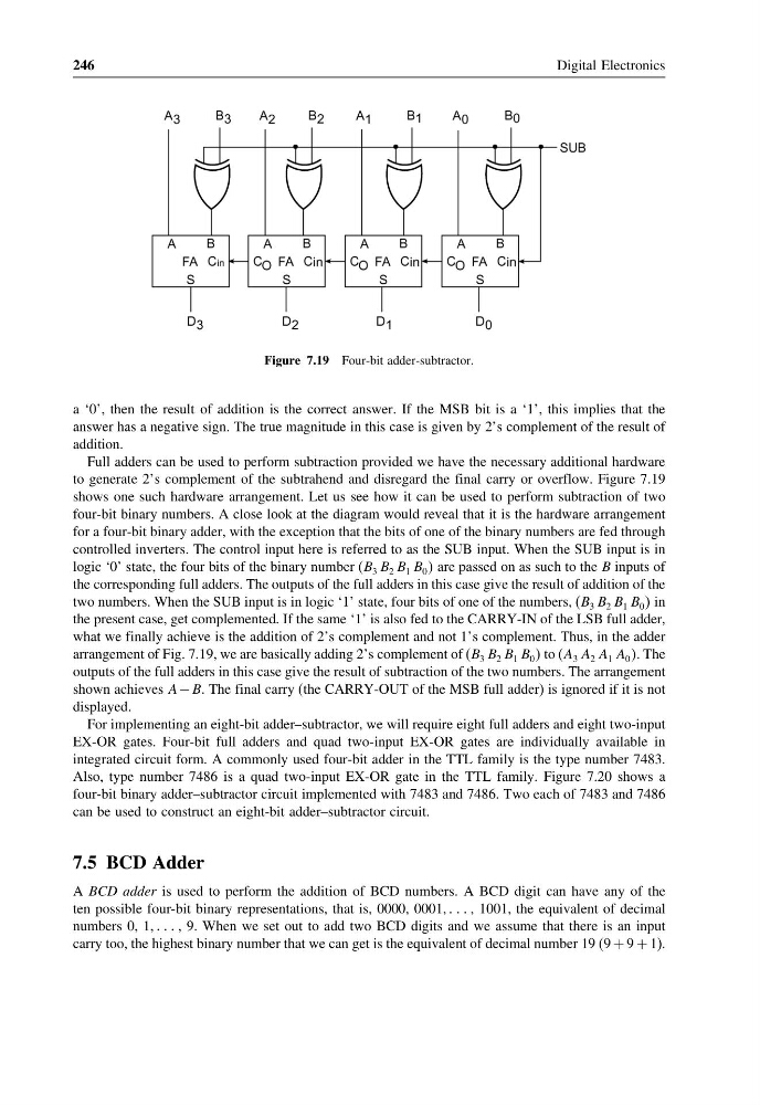
Figure 7.19 Four-bit adder-subtractor.
a ‘0’, then the result of addition is the correct answer. If the MSB bit is a ‘1’, this implies that the
answer has a negative sign. The true magnitude in this case is given by 2’s complement of the result of
addition.
Full adders can be used to perform subtraction provided we have the necessary additional hardware
to generate 2’s complement of the subtrahend and disregard the final carry or overflow. Figure 7.19
shows one such hardware arrangement. Let us see how it can be used to perform subtraction of two
four-bit binary numbers. A close look at the diagram would reveal that it is the hardware arrangement
for a four-bit binary adder, with the exception that the bits of one of the binary numbers are fed through
controlled inverters. The control input here is referred to as the SUB input. When the SUB input is in
logic ‘0’ state, the four bits of the binary number (B 3 B 2 B 1 B 0 are passed on as such to the B inputs of
the corresponding full adders. The outputs of the full adders in this case give the result of addition of the
two numbers. When the SUB input is in logic ‘1’ state, four bits of one of the numbers, (B 3 B 2 B 1 B 0 in
the present case, get complemented. If the same ‘1’ is also fed to the CARRY-IN of the LSB full adder,
what we finally achieve is the addition of 2’s complement and not 1’s complement. Thus, in the adder
arrangement of Fig. 7.19, we are basically adding 2’s complement of (B 3 B 2 B 1 B 0 to (A 3 A 2 A 1 A 0 . The
outputs of the full adders in this case give the result of subtraction of the two numbers. The arrangement
shown achieves A − B. The final carry (the CARRY-OUT of the MSB full adder) is ignored if it is not
displayed.
For implementing an eight-bit adder–subtractor, we will require eight full adders and eight two-input
EX-OR gates. Four-bit full adders and quad two-input EX-OR gates are individually available in
integrated circuit form. A commonly used four-bit adder in the TTL family is the type number 7483.
Also, type number 7486 is a quad two-input EX-OR gate in the TTL family. Figure 7.20 shows a
four-bit binary adder–subtractor circuit implemented with 7483 and 7486. Two each of 7483 and 7486
can be used to construct an eight-bit adder–subtractor circuit.
7.5 BCD Adder
A BCD adder is used to perform the addition of BCD numbers. A BCD digit can have any of the
ten possible four-bit binary representations, that is, 0000, 0001, , 1001, the equivalent of decimal
numbers 0, 1, , 9. When we set out to add two BCD digits and we assume that there is an input
carry too, the highest binary number that we can get is the equivalent of decimal number 19 (9 + 9 + 1).
Digital Electronics
Figure 7.19 Four-bit adder-subtractor.
a ‘0’, then the result of addition is the correct answer. If the MSB bit is a ‘1’, this implies that the
answer has a negative sign. The true magnitude in this case is given by 2’s complement of the result of
addition.
Full adders can be used to perform subtraction provided we have the necessary additional hardware
to generate 2’s complement of the subtrahend and disregard the final carry or overflow. Figure 7.19
shows one such hardware arrangement. Let us see how it can be used to perform subtraction of two
four-bit binary numbers. A close look at the diagram would reveal that it is the hardware arrangement
for a four-bit binary adder, with the exception that the bits of one of the binary numbers are fed through
controlled inverters. The control input here is referred to as the SUB input. When the SUB input is in
logic ‘0’ state, the four bits of the binary number (B 3 B 2 B 1 B 0 are passed on as such to the B inputs of
the corresponding full adders. The outputs of the full adders in this case give the result of addition of the
two numbers. When the SUB input is in logic ‘1’ state, four bits of one of the numbers, (B 3 B 2 B 1 B 0 in
the present case, get complemented. If the same ‘1’ is also fed to the CARRY-IN of the LSB full adder,
what we finally achieve is the addition of 2’s complement and not 1’s complement. Thus, in the adder
arrangement of Fig. 7.19, we are basically adding 2’s complement of (B 3 B 2 B 1 B 0 to (A 3 A 2 A 1 A 0 . The
outputs of the full adders in this case give the result of subtraction of the two numbers. The arrangement
shown achieves A − B. The final carry (the CARRY-OUT of the MSB full adder) is ignored if it is not
displayed.
For implementing an eight-bit adder–subtractor, we will require eight full adders and eight two-input
EX-OR gates. Four-bit full adders and quad two-input EX-OR gates are individually available in
integrated circuit form. A commonly used four-bit adder in the TTL family is the type number 7483.
Also, type number 7486 is a quad two-input EX-OR gate in the TTL family. Figure 7.20 shows a
four-bit binary adder–subtractor circuit implemented with 7483 and 7486. Two each of 7483 and 7486
can be used to construct an eight-bit adder–subtractor circuit.
7.5 BCD Adder
A BCD adder is used to perform the addition of BCD numbers. A BCD digit can have any of the
ten possible four-bit binary representations, that is, 0000, 0001, , 1001, the equivalent of decimal
numbers 0, 1, , 9. When we set out to add two BCD digits and we assume that there is an input
carry too, the highest binary number that we can get is the equivalent of decimal number 19 (9 + 9 + 1).