

242
Digital Electronics
A
0
0
1
1
B
0
1
0
1
D
0
1
1
0
B o
0
1
0
0
A
B
D=A–B
Half
Subtractor
B o
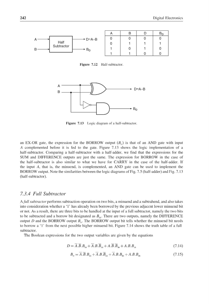
Figure 7.12 Half-subtractor.
A
B
D=A–B
B o
Figure 7.13 Logic diagram of a half-subtractor.
an EX-OR gate, the expression for the BORROW output (B o is that of an AND gate with input
A complemented before it is fed to the gate. Figure 7.13 shows the logic implementation of a
half-subtractor. Comparing a half-subtractor with a half-adder, we find that the expressions for the
SUM and DIFFERENCE outputs are just the same. The expression for BORROW in the case of
the half-subtractor is also similar to what we have for CARRY in the case of the half-adder. If
the input A, that is, the minuend, is complemented, an AND gate can be used to implement the
BORROW output. Note the similarities between the logic diagrams of Fig. 7.5 (half-adder) and Fig. 7.13
(half-subtractor).
7.3.4 Full Subtractor
A full subtractor performs subtraction operation on two bits, a minuend and a subtrahend, and also takes
into consideration whether a ‘1’ has already been borrowed by the previous adjacent lower minuend bit
or not. As a result, there are three bits to be handled at the input of a full subtractor, namely the two bits
to be subtracted and a borrow bit designated as B in . There are two outputs, namely the DIFFERENCE
output D and the BORROW output B o . The BORROW output bit tells whether the minuend bit needs
to borrow a ‘1’ from the next possible higher minuend bit. Figure 7.14 shows the truth table of a full
subtractor.
The Boolean expressions for the two output variables are given by the equations
D = AABBB in + AABBB in + AABBB in + AABBB in
(7.14)
B o = AABBB in + AABBB in + AABBB in + AABBB in
(7.15)
Digital Electronics
A
0
0
1
1
B
0
1
0
1
D
0
1
1
0
B o
0
1
0
0
A
B
D=A–B
Half
Subtractor
B o
Figure 7.12 Half-subtractor.
A
B
D=A–B
B o
Figure 7.13 Logic diagram of a half-subtractor.
an EX-OR gate, the expression for the BORROW output (B o is that of an AND gate with input
A complemented before it is fed to the gate. Figure 7.13 shows the logic implementation of a
half-subtractor. Comparing a half-subtractor with a half-adder, we find that the expressions for the
SUM and DIFFERENCE outputs are just the same. The expression for BORROW in the case of
the half-subtractor is also similar to what we have for CARRY in the case of the half-adder. If
the input A, that is, the minuend, is complemented, an AND gate can be used to implement the
BORROW output. Note the similarities between the logic diagrams of Fig. 7.5 (half-adder) and Fig. 7.13
(half-subtractor).
7.3.4 Full Subtractor
A full subtractor performs subtraction operation on two bits, a minuend and a subtrahend, and also takes
into consideration whether a ‘1’ has already been borrowed by the previous adjacent lower minuend bit
or not. As a result, there are three bits to be handled at the input of a full subtractor, namely the two bits
to be subtracted and a borrow bit designated as B in . There are two outputs, namely the DIFFERENCE
output D and the BORROW output B o . The BORROW output bit tells whether the minuend bit needs
to borrow a ‘1’ from the next possible higher minuend bit. Figure 7.14 shows the truth table of a full
subtractor.
The Boolean expressions for the two output variables are given by the equations
D = AABBB in + AABBB in + AABBB in + AABBB in
(7.14)
B o = AABBB in + AABBB in + AABBB in + AABBB in
(7.15)