

234
Digital Electronics
Combinational
Logic
'n'
Inputs
'm'
Outputs
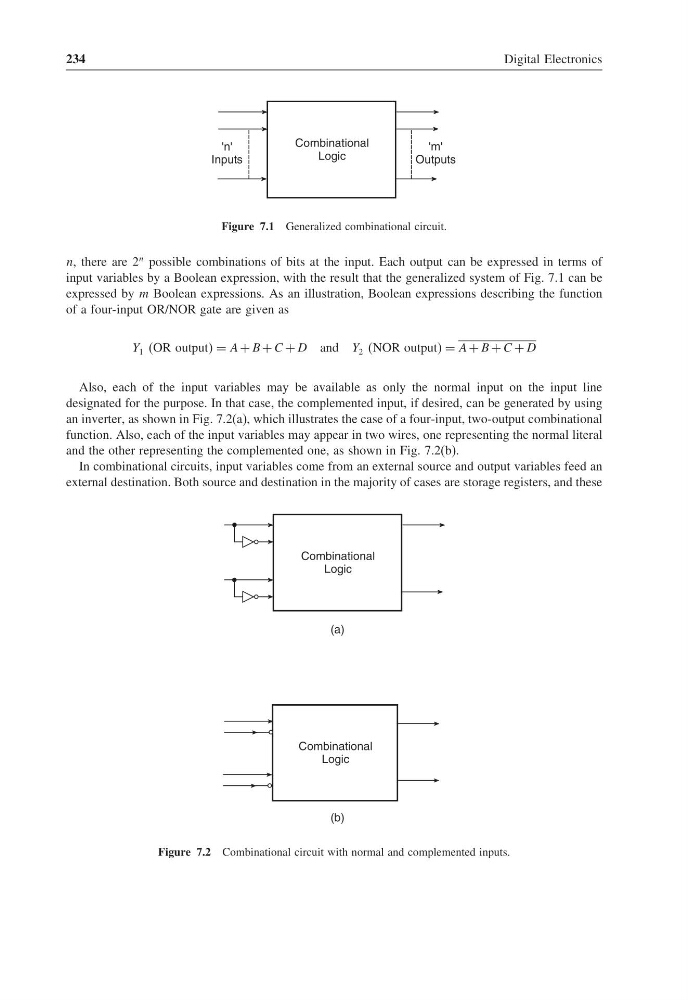
Figure 7.1 Generalized combinational circuit.
n, there are 2
n possible combinations of bits at the input. Each output can be expressed in terms of
input variables by a Boolean expression, with the result that the generalized system of Fig. 7.1 can be
expressed by m Boolean expressions. As an illustration, Boolean expressions describing the function
of a four-input OR/NOR gate are given as
Y 1 OR output = A + B + C + D and Y 2 NOR output = A + B + C + D
Also, each of the input variables may be available as only the normal input on the input line
designated for the purpose. In that case, the complemented input, if desired, can be generated by using
an inverter, as shown in Fig. 7.2(a), which illustrates the case of a four-input, two-output combinational
function. Also, each of the input variables may appear in two wires, one representing the normal literal
and the other representing the complemented one, as shown in Fig. 7.2(b).
In combinational circuits, input variables come from an external source and output variables feed an
external destination. Both source and destination in the majority of cases are storage registers, and these
Combinational
Logic
Combinational
Logic
(a)
(b)
Figure 7.2 Combinational circuit with normal and complemented inputs.
Digital Electronics
Combinational
Logic
'n'
Inputs
'm'
Outputs
Figure 7.1 Generalized combinational circuit.
n, there are 2
n possible combinations of bits at the input. Each output can be expressed in terms of
input variables by a Boolean expression, with the result that the generalized system of Fig. 7.1 can be
expressed by m Boolean expressions. As an illustration, Boolean expressions describing the function
of a four-input OR/NOR gate are given as
Y 1 OR output = A + B + C + D and Y 2 NOR output = A + B + C + D
Also, each of the input variables may be available as only the normal input on the input line
designated for the purpose. In that case, the complemented input, if desired, can be generated by using
an inverter, as shown in Fig. 7.2(a), which illustrates the case of a four-input, two-output combinational
function. Also, each of the input variables may appear in two wires, one representing the normal literal
and the other representing the complemented one, as shown in Fig. 7.2(b).
In combinational circuits, input variables come from an external source and output variables feed an
external destination. Both source and destination in the majority of cases are storage registers, and these
Combinational
Logic
Combinational
Logic
(a)
(b)
Figure 7.2 Combinational circuit with normal and complemented inputs.