

216
Digital Electronics
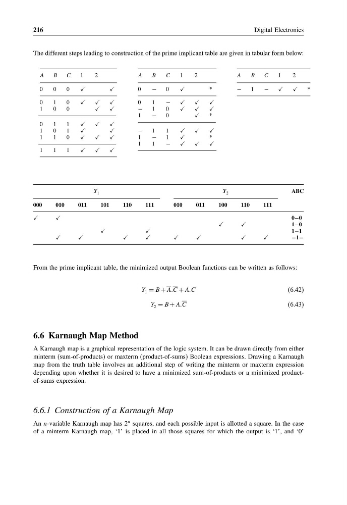
The different steps leading to construction of the prime implicant table are given in tabular form below:
A
B
C
1
2
A
B
C
1
2
A
B
C
1
2
0
0
0
0
−
0
*
−
1
−
*
0
1
0
0
1
−
1
0
0
−
1
0
1
−
0
*
0
1
1
1
0
1
−
1
1
1
1
0
1
−
1
*
1
1
−
1
1
1
Y 1
Y 2
ABC
000
010
011
101
110
111
010
011
100
110
111
0−0
1−0
1−1
−1−
From the prime implicant table, the minimized output Boolean functions can be written as follows:
Y 1 = B + AAC + AAC
(6.42)
Y 2 = B + AAC
(6.43)
6.6 Karnaugh Map Method
A Karnaugh map is a graphical representation of the logic system. It can be drawn directly from either
minterm (sum-of-products) or maxterm (product-of-sums) Boolean expressions. Drawing a Karnaugh
map from the truth table involves an additional step of writing the minterm or maxterm expression
depending upon whether it is desired to have a minimized sum-of-products or a minimized productof-sums expression.
6.6.1 Construction of a Karnaugh Map
An n-variable Karnaugh map has 2
n squares, and each possible input is allotted a square. In the case
of a minterm Karnaugh map, ‘1’ is placed in all those squares for which the output is ‘1’, and ‘0’
Digital Electronics
The different steps leading to construction of the prime implicant table are given in tabular form below:
A
B
C
1
2
A
B
C
1
2
A
B
C
1
2
0
0
0
0
−
0
*
−
1
−
*
0
1
0
0
1
−
1
0
0
−
1
0
1
−
0
*
0
1
1
1
0
1
−
1
1
1
1
0
1
−
1
*
1
1
−
1
1
1
Y 1
Y 2
ABC
000
010
011
101
110
111
010
011
100
110
111
0−0
1−0
1−1
−1−
From the prime implicant table, the minimized output Boolean functions can be written as follows:
Y 1 = B + AAC + AAC
(6.42)
Y 2 = B + AAC
(6.43)
6.6 Karnaugh Map Method
A Karnaugh map is a graphical representation of the logic system. It can be drawn directly from either
minterm (sum-of-products) or maxterm (product-of-sums) Boolean expressions. Drawing a Karnaugh
map from the truth table involves an additional step of writing the minterm or maxterm expression
depending upon whether it is desired to have a minimized sum-of-products or a minimized productof-sums expression.
6.6.1 Construction of a Karnaugh Map
An n-variable Karnaugh map has 2
n squares, and each possible input is allotted a square. In the case
of a minterm Karnaugh map, ‘1’ is placed in all those squares for which the output is ‘1’, and ‘0’