

212
Digital Electronics
A
B
C
D
A
B
C
D
A
B
C
D
A B
C
D
0
1
0
1
0
1
0
1
0
1
−
1
− 1
−
1
*
0
1
1
1
−
1
0
1
1
1
0
1
0
1
1
1
1
1
1
0
1
1
0
1
−
1
1
1
1
1
1
1
1
1
1
0
1
1
−
1
1
1
1
−
*
1
1
1
1
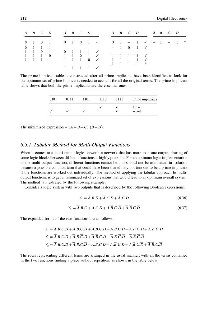
The prime implicant table is constructed after all prime implicants have been identified to look for
the optimum set of prime implicants needed to account for all the original terms. The prime implicant
table shows that both the prime implicants are the essential ones:
0101
0111
1101
1110
1111
Prime implicants
111−
−1−1
The minimized expression = A + B + CCCCB + DD.
6.5.1 Tabular Method for Multi-Output Functions
When it comes to a multi-output logic network, a network that has more than one output, sharing of
some logic blocks between different functions is highly probable. For an optimum logic implementation
of the multi-output function, different functions cannot be and should not be minimized in isolation
because a possible common term that could have been shared may not turn out to be a prime implicant
if the functions are worked out individually. The method of applying the tabular approach to multioutput functions is to get a minimized set of expressions that would lead to an optimum overall system.
The method is illustrated by the following example.
Consider a logic system with two outputs that is described by the following Boolean expressions:
Y 1 = AABBD + AACCD + AACCD
(6.36)
Y 2 = AABBC + AACCD + AABBCCD + AABBCCD
(6.37)
The expanded forms of the two functions are as follows:
Y 1 = AABBCCD + AABBCCD + AABBCCD + AABBCCD + AABBCCD + AABBCCD
Y 1 = AABBCCD + AABBCCD + AABBCCD + AABBCCD + AABBCCD
Y 2 = AABBCCD + AABBCCD + AABBCCD + AABBCCD + AABBCCD + AABBCCD
The rows representing different terms are arranged in the usual manner, with all the terms contained
in the two functions finding a place without repetition, as shown in the table below:
Digital Electronics
A
B
C
D
A
B
C
D
A
B
C
D
A B
C
D
0
1
0
1
0
1
0
1
0
1
−
1
− 1
−
1
*
0
1
1
1
−
1
0
1
1
1
0
1
0
1
1
1
1
1
1
0
1
1
0
1
−
1
1
1
1
1
1
1
1
1
1
0
1
1
−
1
1
1
1
−
*
1
1
1
1
The prime implicant table is constructed after all prime implicants have been identified to look for
the optimum set of prime implicants needed to account for all the original terms. The prime implicant
table shows that both the prime implicants are the essential ones:
0101
0111
1101
1110
1111
Prime implicants
111−
−1−1
The minimized expression = A + B + CCCCB + DD.
6.5.1 Tabular Method for Multi-Output Functions
When it comes to a multi-output logic network, a network that has more than one output, sharing of
some logic blocks between different functions is highly probable. For an optimum logic implementation
of the multi-output function, different functions cannot be and should not be minimized in isolation
because a possible common term that could have been shared may not turn out to be a prime implicant
if the functions are worked out individually. The method of applying the tabular approach to multioutput functions is to get a minimized set of expressions that would lead to an optimum overall system.
The method is illustrated by the following example.
Consider a logic system with two outputs that is described by the following Boolean expressions:
Y 1 = AABBD + AACCD + AACCD
(6.36)
Y 2 = AABBC + AACCD + AABBCCD + AABBCCD
(6.37)
The expanded forms of the two functions are as follows:
Y 1 = AABBCCD + AABBCCD + AABBCCD + AABBCCD + AABBCCD + AABBCCD
Y 1 = AABBCCD + AABBCCD + AABBCCD + AABBCCD + AABBCCD
Y 2 = AABBCCD + AABBCCD + AABBCCD + AABBCCD + AABBCCD + AABBCCD
The rows representing different terms are arranged in the usual manner, with all the terms contained
in the two functions finding a place without repetition, as shown in the table below: