

Logic Families
145
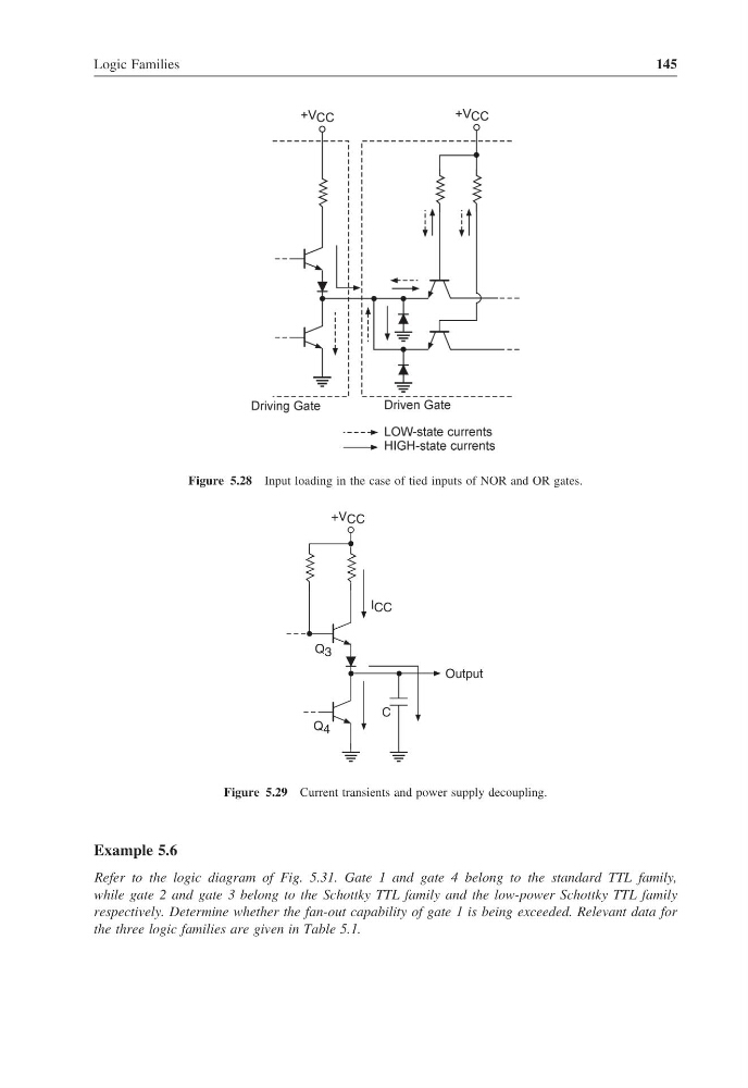
Figure 5.28 Input loading in the case of tied inputs of NOR and OR gates.
C
+V CC
I CC
Output
Q 4
Q 3
Figure 5.29 Current transients and power supply decoupling.
Example 5.6
Refer to the logic diagram of Fig. 5.31. Gate 1 and gate 4 belong to the standard TTL family,
while gate 2 and gate 3 belong to the Schottky TTL family and the low-power Schottky TTL family
respectively. Determine whether the fan-out capability of gate 1 is being exceeded. Relevant data for
the three logic families are given in Table 5.1.
145
Figure 5.28 Input loading in the case of tied inputs of NOR and OR gates.
C
+V CC
I CC
Output
Q 4
Q 3
Figure 5.29 Current transients and power supply decoupling.
Example 5.6
Refer to the logic diagram of Fig. 5.31. Gate 1 and gate 4 belong to the standard TTL family,
while gate 2 and gate 3 belong to the Schottky TTL family and the low-power Schottky TTL family
respectively. Determine whether the fan-out capability of gate 1 is being exceeded. Relevant data for
the three logic families are given in Table 5.1.