

Logic Families
121
• Supply current, I CC . The supply current when the output is HIGH, LOW and in the high-impedance
state is respectively designated as I CCH , I CCL and I CCZ .
• Rise time, t r . This is the time that elapses between 10 and 90 % of the final signal level when the
signal is making a transition from logic LOW to logic HIGH.
• Fall time, t f . This is the time that elapses between 90 and 10 % of the signal level when it is making
HIGH to LOW transition.
• Propagation delay t p . The propagation delay is the time delay between the occurrence of change
in the logical level at the input and before it is reflected at the output. It is the time delay between
the specified voltage points on the input and output waveforms. Propagation delays are separately
defined for LOW-to-HIGH and HIGH-to-LOW transitions at the output. In addition, we also define
enable and disable time delays that occur during transition between the high-impedance state and
defined logic LOW or HIGH states.
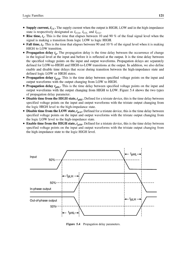
• Propagation delay t pLH . This is the time delay between specified voltage points on the input and
output waveforms with the output changing from LOW to HIGH.
• Propagation delay t pHL . This is the time delay between specified voltage points on the input and
output waveforms with the output changing from HIGH to LOW. Figure 5.4 shows the two types
of propagation delay parameter.
• Disable time from the HIGH state, t pHZ . Defined for a tristate device, this is the time delay between
specified voltage points on the input and output waveforms with the tristate output changing from
the logic HIGH level to the high-impedance state.
• Disable time from the LOW state, t pLZ . Defined for a tristate device, this is the time delay between
specified voltage points on the input and output waveforms with the tristate output changing from
the logic LOW level to the high-impedance state.
• Enable time from the HIGH state, t pZH . Defined for a tristate device, this is the time delay between
specified voltage points on the input and output waveforms with the tristate output changing from
the high-impedance state to the logic HIGH level.
Figure 5.4 Propagation delay parameters.
121
• Supply current, I CC . The supply current when the output is HIGH, LOW and in the high-impedance
state is respectively designated as I CCH , I CCL and I CCZ .
• Rise time, t r . This is the time that elapses between 10 and 90 % of the final signal level when the
signal is making a transition from logic LOW to logic HIGH.
• Fall time, t f . This is the time that elapses between 90 and 10 % of the signal level when it is making
HIGH to LOW transition.
• Propagation delay t p . The propagation delay is the time delay between the occurrence of change
in the logical level at the input and before it is reflected at the output. It is the time delay between
the specified voltage points on the input and output waveforms. Propagation delays are separately
defined for LOW-to-HIGH and HIGH-to-LOW transitions at the output. In addition, we also define
enable and disable time delays that occur during transition between the high-impedance state and
defined logic LOW or HIGH states.
• Propagation delay t pLH . This is the time delay between specified voltage points on the input and
output waveforms with the output changing from LOW to HIGH.
• Propagation delay t pHL . This is the time delay between specified voltage points on the input and
output waveforms with the output changing from HIGH to LOW. Figure 5.4 shows the two types
of propagation delay parameter.
• Disable time from the HIGH state, t pHZ . Defined for a tristate device, this is the time delay between
specified voltage points on the input and output waveforms with the tristate output changing from
the logic HIGH level to the high-impedance state.
• Disable time from the LOW state, t pLZ . Defined for a tristate device, this is the time delay between
specified voltage points on the input and output waveforms with the tristate output changing from
the logic LOW level to the high-impedance state.
• Enable time from the HIGH state, t pZH . Defined for a tristate device, this is the time delay between
specified voltage points on the input and output waveforms with the tristate output changing from
the high-impedance state to the logic HIGH level.
Figure 5.4 Propagation delay parameters.