

88
Digital Electronics
A
0
0
0
0
1
1
1
1
B
0
0
1
1
0
0
1
1
E
0
1
0
1
0
1
0
1
Y
Z
1
Z
1
Z
1
Z
0
(a)
A
Y
B
E
A
Y
B
E
A
0
0
0
0
1
1
1
1
B
0
0
1
1
0
0
1
1
E
0
1
0
1
0
1
0
1
Y
1
Z
1
Z
1
Z
0
Z
(b)
Z= High Impedance state
Z= High Impedance state
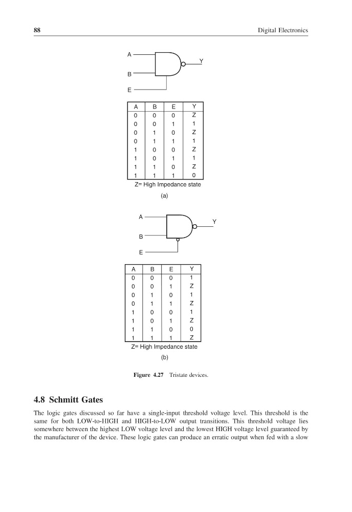
Figure 4.27 Tristate devices.
4.8 Schmitt Gates
The logic gates discussed so far have a single-input threshold voltage level. This threshold is the
same for both LOW-to-HIGH and HIGH-to-LOW output transitions. This threshold voltage lies
somewhere between the highest LOW voltage level and the lowest HIGH voltage level guaranteed by
the manufacturer of the device. These logic gates can produce an erratic output when fed with a slow
Digital Electronics
A
0
0
0
0
1
1
1
1
B
0
0
1
1
0
0
1
1
E
0
1
0
1
0
1
0
1
Y
Z
1
Z
1
Z
1
Z
0
(a)
A
Y
B
E
A
Y
B
E
A
0
0
0
0
1
1
1
1
B
0
0
1
1
0
0
1
1
E
0
1
0
1
0
1
0
1
Y
1
Z
1
Z
1
Z
0
Z
(b)
Z= High Impedance state
Z= High Impedance state
Figure 4.27 Tristate devices.
4.8 Schmitt Gates
The logic gates discussed so far have a single-input threshold voltage level. This threshold is the
same for both LOW-to-HIGH and HIGH-to-LOW output transitions. This threshold voltage lies
somewhere between the highest LOW voltage level and the lowest HIGH voltage level guaranteed by
the manufacturer of the device. These logic gates can produce an erratic output when fed with a slow