

70 Basic Seismological Theory
interface in turn generates another four rays at the next interface, and so on. Because Snell’s law applies at each interface, all
these rays have the same ray parameter. As a result, p is
constant along any ray path, no matter how many transmissions, reflections, or conversions the ray has undergone. This
gives a way of tracing the ray path for a ray that began its
travels with a certain ray parameter. In doing this on a computer, an advantage of the ray parameter is that it is zero for a
vertically incident wave, whereas c x is infinite.
2.5.8 Waveguides
Snell’s law is one of seismology’s most important tools,
because seismic waves encounter variations in velocity due to
changes in the physical properties of the materials, including
the effects of composition, temperature, and pressure. In general, the velocity increases with depth, so seismic waves turn
toward the horizontal as they go deeper. Eventually the ray
“bottoms,” turns upward, and reaches the surface (Fig. 1.1-3).
Such ray paths can be modeled using Snell’s law, either with
many layers or with a version (Section 3.4) accommodating
velocities that vary smoothly with depth and so give smooth
ray paths. The ray path and the travel time along it thus provide
information about the distribution of seismic velocities and
physical properties with depth.
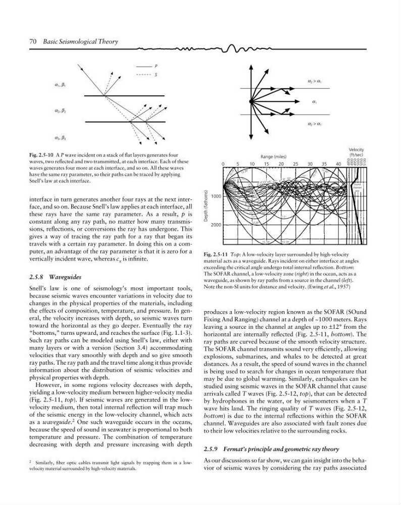
However, in some regions velocity decreases with depth,
yielding a low-velocity medium between higher-velocity media
(Fig. 2.5-11, top). If seismic waves are generated in the lowvelocity medium, then total internal reflection will trap much
of the seismic energy in the low-velocity channel, which acts
as a waveguide. 2 One such waveguide occurs in the oceans,
because the speed of sound in seawater is proportional to both
temperature and pressure. The combination of temperature
decreasing with depth and pressure increasing with depth
Fig. 2.5-10 A P wave incident on a stack of flat layers generates four
waves, two reflected and two transmitted, at each interface. Each of these
waves generates four more at each interface, and so on. All these waves
have the same ray parameter, so their paths can be traced by applying
Snell’s law at each interface.
α 3 , 3
β
P
S
α 1 , 1
β
α 2 , 2
β
2 Similarly, fiber optic cables transmit light signals by trapping them in a lowvelocity material surrounded by high-velocity materials.
Depth (fathoms)
1000
2000
2°
3°
4°
5°
6°
7°
8°
9°
10°
11°
12.20°
15.19°
15.19°
11°
10°
9°
8°
7°
6°
5°
4°
3°
2°
11 °
1 0 °
1 5 .1 9 °
12 .2 0°
3°
4° 5° 6° 7° 8°
9° 10°
1 5 .1 9 °
11°
12 .2 0°
Sound
channel
axis
0
5
10
15
20
25
30
35
40
Range (miles)
4850
4900
4950
5000
5050
5100
Velocity
(ft/sec)
α 1
α
α 2 > α 1
α α
α 2 > α 1
α α
Fig. 2.5-11 Top: A low-velocity layer surrounded by high-velocity
material acts as a waveguide. Rays incident on either interface at angles
exceeding the critical angle undergo total internal reflection. Bottom:
The SOFAR channel, a low-velocity zone (right) in the ocean, acts as a
waveguide, as shown by ray paths from a source in the channel (left).
Note the non-SI units for distance and velocity. (Ewing et al., 1957)
produces a low-velocity region known as the SOFAR (SOund
Fixing And Ranging) channel at a depth of ~1000 meters. Rays
leaving a source in the channel at angles up to ±12° from the
horizontal are internally reflected (Fig. 2.5-11, bottom). The
ray paths are curved because of the smooth velocity structure.
The SOFAR channel transmits sound very efficiently, allowing
explosions, submarines, and whales to be detected at great
distances. As a result, the speed of sound waves in the channel
is being used to search for changes in ocean temperature that
may be due to global warming. Similarly, earthquakes can be
studied using seismic waves in the SOFAR channel that cause
arrivals called T waves (Fig. 2.5-12, top), that can be detected
by hydrophones in the water, or by seismometers when a T
wave hits land. The ringing quality of T waves (Fig. 2.5-12,
bottom) is due to the internal reflections within the SOFAR
channel. Waveguides are also associated with fault zones due
to their low velocities relative to the surrounding rocks.
2.5.9 Fermat’s principle and geometric ray theory
As our discussions so far show, we can gain insight into the behavior of seismic waves by considering the ray paths associated
interface in turn generates another four rays at the next interface, and so on. Because Snell’s law applies at each interface, all
these rays have the same ray parameter. As a result, p is
constant along any ray path, no matter how many transmissions, reflections, or conversions the ray has undergone. This
gives a way of tracing the ray path for a ray that began its
travels with a certain ray parameter. In doing this on a computer, an advantage of the ray parameter is that it is zero for a
vertically incident wave, whereas c x is infinite.
2.5.8 Waveguides
Snell’s law is one of seismology’s most important tools,
because seismic waves encounter variations in velocity due to
changes in the physical properties of the materials, including
the effects of composition, temperature, and pressure. In general, the velocity increases with depth, so seismic waves turn
toward the horizontal as they go deeper. Eventually the ray
“bottoms,” turns upward, and reaches the surface (Fig. 1.1-3).
Such ray paths can be modeled using Snell’s law, either with
many layers or with a version (Section 3.4) accommodating
velocities that vary smoothly with depth and so give smooth
ray paths. The ray path and the travel time along it thus provide
information about the distribution of seismic velocities and
physical properties with depth.
However, in some regions velocity decreases with depth,
yielding a low-velocity medium between higher-velocity media
(Fig. 2.5-11, top). If seismic waves are generated in the lowvelocity medium, then total internal reflection will trap much
of the seismic energy in the low-velocity channel, which acts
as a waveguide. 2 One such waveguide occurs in the oceans,
because the speed of sound in seawater is proportional to both
temperature and pressure. The combination of temperature
decreasing with depth and pressure increasing with depth
Fig. 2.5-10 A P wave incident on a stack of flat layers generates four
waves, two reflected and two transmitted, at each interface. Each of these
waves generates four more at each interface, and so on. All these waves
have the same ray parameter, so their paths can be traced by applying
Snell’s law at each interface.
α 3 , 3
β
P
S
α 1 , 1
β
α 2 , 2
β
2 Similarly, fiber optic cables transmit light signals by trapping them in a lowvelocity material surrounded by high-velocity materials.
Depth (fathoms)
1000
2000
2°
3°
4°
5°
6°
7°
8°
9°
10°
11°
12.20°
15.19°
15.19°
11°
10°
9°
8°
7°
6°
5°
4°
3°
2°
11 °
1 0 °
1 5 .1 9 °
12 .2 0°
3°
4° 5° 6° 7° 8°
9° 10°
1 5 .1 9 °
11°
12 .2 0°
Sound
channel
axis
0
5
10
15
20
25
30
35
40
Range (miles)
4850
4900
4950
5000
5050
5100
Velocity
(ft/sec)
α 1
α
α 2 > α 1
α α
α 2 > α 1
α α
Fig. 2.5-11 Top: A low-velocity layer surrounded by high-velocity
material acts as a waveguide. Rays incident on either interface at angles
exceeding the critical angle undergo total internal reflection. Bottom:
The SOFAR channel, a low-velocity zone (right) in the ocean, acts as a
waveguide, as shown by ray paths from a source in the channel (left).
Note the non-SI units for distance and velocity. (Ewing et al., 1957)
produces a low-velocity region known as the SOFAR (SOund
Fixing And Ranging) channel at a depth of ~1000 meters. Rays
leaving a source in the channel at angles up to ±12° from the
horizontal are internally reflected (Fig. 2.5-11, bottom). The
ray paths are curved because of the smooth velocity structure.
The SOFAR channel transmits sound very efficiently, allowing
explosions, submarines, and whales to be detected at great
distances. As a result, the speed of sound waves in the channel
is being used to search for changes in ocean temperature that
may be due to global warming. Similarly, earthquakes can be
studied using seismic waves in the SOFAR channel that cause
arrivals called T waves (Fig. 2.5-12, top), that can be detected
by hydrophones in the water, or by seismometers when a T
wave hits land. The ringing quality of T waves (Fig. 2.5-12,
bottom) is due to the internal reflections within the SOFAR
channel. Waveguides are also associated with fault zones due
to their low velocities relative to the surrounding rocks.
2.5.9 Fermat’s principle and geometric ray theory
As our discussions so far show, we can gain insight into the behavior of seismic waves by considering the ray paths associated