

68 Basic Seismological Theory
x
z
α 1
i c
α
α 2
α
α 1
α
>
Medium 1
Medium 2
Fig. 2.5-7 Illustration of the critical angle i c for P waves incident on a
faster medium. The transmitted S and the reflected P and S waves are not
shown. As the angle of incidence increases, the incoming waves become
more nearly horizontal, and the refracted P waves approach the interface.
For waves incident at an angle exceeding (more horizontal than) the
critical angle, no traveling P wave is transmitted into medium 2.
in the next section, the P-wave potential for the second medium
has a z-dependent real exponential term, exp (−k z z), instead of
a purely imaginary exponential term, exp (−ik z z). Hence the
displacement in the second medium is not a propagating plane
wave, but occurs as an evanescent wave that travels along the
interface and decays away from the interface.
Although for angles of incidence beyond the critical angle
there is no transmitted P wave, there can still be a transmitted
S wave. If the S velocity in medium 2 is greater than the P velocity in medium 1 there is a second critical angle
sin i c 2 = α 1 /β 2
(28)
beyond which no transmitted P or S waves occur.
2.5.6 Snell’s law for SH waves
Snell’s law also applies to SH waves. Because for SH waves the
displacement satisfies the wave equation, SH waves in the first
medium are described by
u y (x, z, t) = B 1 exp (i(ωt − k x x − k x r β 1 z))
+ B 2 exp (i(ωt − k x x + k x r β 1 z)),
(29)
where B 1 and B 2 are the amplitudes of the incoming and
reflected SH waves (Fig. 2.5-8). In the second medium, the
transmitted SH wave is
u y (x, z, t) = B′ exp (i(ωt − k x x − k x r β 2 z)).
(30)
As before, Snell’s law
c x = β 1 /sin j 1 = β 2 /sin j 2
(31)
Incident
SV
S V p a r t ic le m o t io n
Reflected
P
Incident
SV
Reflected
SV
Transmitted
SV
Transmitted
P
Propagation direction
of boundary
disturbance
(c)
(b)
(a)
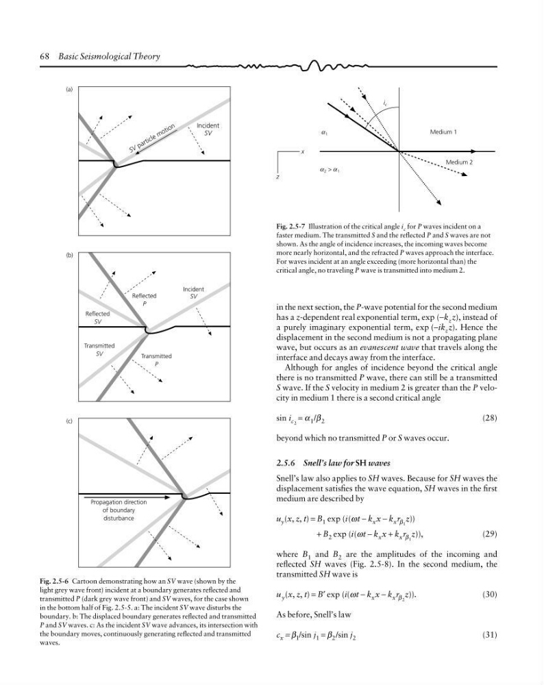
Fig. 2.5-6 Cartoon demonstrating how an SV wave (shown by the
light grey wave front) incident at a boundary generates reflected and
transmitted P (dark grey wave front) and SV waves, for the case shown
in the bottom half of Fig. 2.5-5. a: The incident SV wave disturbs the
boundary. b: The displaced boundary generates reflected and transmitted
P and SV waves. c: As the incident SV wave advances, its intersection with
the boundary moves, continuously generating reflected and transmitted
waves.
x
z
α 1
i c
α
α 2
α
α 1
α
>
Medium 1
Medium 2
Fig. 2.5-7 Illustration of the critical angle i c for P waves incident on a
faster medium. The transmitted S and the reflected P and S waves are not
shown. As the angle of incidence increases, the incoming waves become
more nearly horizontal, and the refracted P waves approach the interface.
For waves incident at an angle exceeding (more horizontal than) the
critical angle, no traveling P wave is transmitted into medium 2.
in the next section, the P-wave potential for the second medium
has a z-dependent real exponential term, exp (−k z z), instead of
a purely imaginary exponential term, exp (−ik z z). Hence the
displacement in the second medium is not a propagating plane
wave, but occurs as an evanescent wave that travels along the
interface and decays away from the interface.
Although for angles of incidence beyond the critical angle
there is no transmitted P wave, there can still be a transmitted
S wave. If the S velocity in medium 2 is greater than the P velocity in medium 1 there is a second critical angle
sin i c 2 = α 1 /β 2
(28)
beyond which no transmitted P or S waves occur.
2.5.6 Snell’s law for SH waves
Snell’s law also applies to SH waves. Because for SH waves the
displacement satisfies the wave equation, SH waves in the first
medium are described by
u y (x, z, t) = B 1 exp (i(ωt − k x x − k x r β 1 z))
+ B 2 exp (i(ωt − k x x + k x r β 1 z)),
(29)
where B 1 and B 2 are the amplitudes of the incoming and
reflected SH waves (Fig. 2.5-8). In the second medium, the
transmitted SH wave is
u y (x, z, t) = B′ exp (i(ωt − k x x − k x r β 2 z)).
(30)
As before, Snell’s law
c x = β 1 /sin j 1 = β 2 /sin j 2
(31)
Incident
SV
S V p a r t ic le m o t io n
Reflected
P
Incident
SV
Reflected
SV
Transmitted
SV
Transmitted
P
Propagation direction
of boundary
disturbance
(c)
(b)
(a)
Fig. 2.5-6 Cartoon demonstrating how an SV wave (shown by the
light grey wave front) incident at a boundary generates reflected and
transmitted P (dark grey wave front) and SV waves, for the case shown
in the bottom half of Fig. 2.5-5. a: The incident SV wave disturbs the
boundary. b: The displaced boundary generates reflected and transmitted
P and SV waves. c: As the incident SV wave advances, its intersection with
the boundary moves, continuously generating reflected and transmitted
waves.