

3.3 Reflection seismology 153
Position
on trace
Diffraction
hyperbola
Point diffractor
(x 0 , z 0 , t = 0)
True position
Seismic section
x
vt
x
z
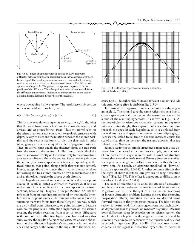
Fig. 3.3-33 Effect of a point source or diffractor. Left: The point
diffractor acts as a source of spherical (circular in two dimensions) wave
fronts. Right: The resulting seismic section with time scaled by velocity
so that the vertical axis has the dimensions of distance. The diffraction
appears as a hyperbola. The point at the apex corresponds to the true
position of the diffractor. The other points are due to later arrivals from
the diffractor at nonvertical incidence, so their positions on the section
do not indicate a reflector directly below the receiver.
Fig. 3.3-34 Diffraction hyperbola with true amplitudes.
(After Claerbout, 1985.)
cause Eqn 71 describes only the travel times, it does not include
this term, whose effect is visible in Fig. 3.3-34.
To illustrate this approach, consider an interface dipping at
an angle β. This should give the same reflections as a line of
closely spaced point diffractors, so the seismic section will be
a sum of the resulting hyperbolas. As shown in Fig. 3.3-35,
the hyperbolas interfere constructively, causing an apparent
interface. Interestingly, this apparent interface does not pass
through the apex of each hyperbola, so it is displaced from
the real interface and appears to have a shallower dip angle, α.
Because the scaled travel time to the true interface equals the
scaled arrival time on the trace, the real and apparent dips are
related by sin β = tan α.
Seismic sections from simple structures can appear quite different from the actual structure. For example, consideration
of ray paths for a single reflector with a synclinal structure
shows that several arrivals from different points on the reflector appear on a single zero-offset trace, each with a different
travel time. As a result, an apparent anticlinal, or “bowtie,”
structure appears (Fig. 3.3-36). Another common effect is that
the edges of sharp interfaces can give rise to long diffraction
“tails” (Fig. 3.3-37). This effect is analogous to diffraction at
the edges of a slit (Fig. 2.5-18).
The goal of migration is to undo the effects of diffraction
and hence convert the data to realistic images of the subsurface.
Migration can thus be thought of as an inverse scattering
or inverse diffraction problem. Because this requires removing
propagation effects, migration methods are derived using
forward models of the propagation process. The idea that the
section is the sum of diffractions suggests one approach known
as diffraction sum migration, or Kirchoff migration. Because
point diffractors cause hyperbolas on the seismic section, the
amplitude of each point on the migrated section is found by
summing the unmigrated section with appropriate scaling along
hyperbolic trajectories (Fig. 3.3-38). This operation should
collapse all the signal in diffraction hyperbolas to points at
whose downgoing half we ignore. The resulting seismic section
is the wave field at the surface, z = 0,
u(x, 0, t) = δ ((x − x 0 ) 2 + (z 0 ) 2 − (vt) 2 ).
(71)
This is a hyperbola with apex at (x = x 0 , t = z 0 /v), showing
that the wave front arrives first directly above the source, and
arrives later at points farther away. Thus the arrival seen on
the seismic section is not equivalent to geologic structure with
depth. A way to visualize the relation between the source position and the seismic section is to plot the time axis in units
of vt, giving a time scale equal to the propagation distance.
Thus an arrival time equals the distance along the true path
from the source to the receiver. As illustrated, the depth of the
source is shown correctly on the section only by the arrival time
at a receiver directly above the source. For all other points on
the surface, the arrival appears at a time corresponding to the
travel time to that point, along a path that was not vertical.
Hence, except above the source, the arrival on the section does
not correspond to a source directly below the receiver, and the
arrival time does not give the source depth directly.
The hyperbolic arrival on a seismic section due to a point
source at depth is called a diffraction hyperbola. It lets us
understand how complicated structures appear on seismic
sections, because by Huygens’ principle (Section 2.5.10) the
reflection from an interface can be found by treating the interface as a set of point sources. The resulting reflection is found by
summing the wave fronts from these Huygens’ sources, which
are also called point diffractors, or point scatterers. Because
each source produces a diffraction hyperbola on the seismic
section, the section resulting from a set of point diffractors
is the sum of their diffraction hyperbolas. In considering this
sum, we use the results of a more sophisticated analysis showing that the diffraction hyperbola’s amplitude is largest at the
apex and decays as the cosine of the angle off to the sides. Be-
Position
on trace
Diffraction
hyperbola
Point diffractor
(x 0 , z 0 , t = 0)
True position
Seismic section
x
vt
x
z
Fig. 3.3-33 Effect of a point source or diffractor. Left: The point
diffractor acts as a source of spherical (circular in two dimensions) wave
fronts. Right: The resulting seismic section with time scaled by velocity
so that the vertical axis has the dimensions of distance. The diffraction
appears as a hyperbola. The point at the apex corresponds to the true
position of the diffractor. The other points are due to later arrivals from
the diffractor at nonvertical incidence, so their positions on the section
do not indicate a reflector directly below the receiver.
Fig. 3.3-34 Diffraction hyperbola with true amplitudes.
(After Claerbout, 1985.)
cause Eqn 71 describes only the travel times, it does not include
this term, whose effect is visible in Fig. 3.3-34.
To illustrate this approach, consider an interface dipping at
an angle β. This should give the same reflections as a line of
closely spaced point diffractors, so the seismic section will be
a sum of the resulting hyperbolas. As shown in Fig. 3.3-35,
the hyperbolas interfere constructively, causing an apparent
interface. Interestingly, this apparent interface does not pass
through the apex of each hyperbola, so it is displaced from
the real interface and appears to have a shallower dip angle, α.
Because the scaled travel time to the true interface equals the
scaled arrival time on the trace, the real and apparent dips are
related by sin β = tan α.
Seismic sections from simple structures can appear quite different from the actual structure. For example, consideration
of ray paths for a single reflector with a synclinal structure
shows that several arrivals from different points on the reflector appear on a single zero-offset trace, each with a different
travel time. As a result, an apparent anticlinal, or “bowtie,”
structure appears (Fig. 3.3-36). Another common effect is that
the edges of sharp interfaces can give rise to long diffraction
“tails” (Fig. 3.3-37). This effect is analogous to diffraction at
the edges of a slit (Fig. 2.5-18).
The goal of migration is to undo the effects of diffraction
and hence convert the data to realistic images of the subsurface.
Migration can thus be thought of as an inverse scattering
or inverse diffraction problem. Because this requires removing
propagation effects, migration methods are derived using
forward models of the propagation process. The idea that the
section is the sum of diffractions suggests one approach known
as diffraction sum migration, or Kirchoff migration. Because
point diffractors cause hyperbolas on the seismic section, the
amplitude of each point on the migrated section is found by
summing the unmigrated section with appropriate scaling along
hyperbolic trajectories (Fig. 3.3-38). This operation should
collapse all the signal in diffraction hyperbolas to points at
whose downgoing half we ignore. The resulting seismic section
is the wave field at the surface, z = 0,
u(x, 0, t) = δ ((x − x 0 ) 2 + (z 0 ) 2 − (vt) 2 ).
(71)
This is a hyperbola with apex at (x = x 0 , t = z 0 /v), showing
that the wave front arrives first directly above the source, and
arrives later at points farther away. Thus the arrival seen on
the seismic section is not equivalent to geologic structure with
depth. A way to visualize the relation between the source position and the seismic section is to plot the time axis in units
of vt, giving a time scale equal to the propagation distance.
Thus an arrival time equals the distance along the true path
from the source to the receiver. As illustrated, the depth of the
source is shown correctly on the section only by the arrival time
at a receiver directly above the source. For all other points on
the surface, the arrival appears at a time corresponding to the
travel time to that point, along a path that was not vertical.
Hence, except above the source, the arrival on the section does
not correspond to a source directly below the receiver, and the
arrival time does not give the source depth directly.
The hyperbolic arrival on a seismic section due to a point
source at depth is called a diffraction hyperbola. It lets us
understand how complicated structures appear on seismic
sections, because by Huygens’ principle (Section 2.5.10) the
reflection from an interface can be found by treating the interface as a set of point sources. The resulting reflection is found by
summing the wave fronts from these Huygens’ sources, which
are also called point diffractors, or point scatterers. Because
each source produces a diffraction hyperbola on the seismic
section, the section resulting from a set of point diffractors
is the sum of their diffraction hyperbolas. In considering this
sum, we use the results of a more sophisticated analysis showing that the diffraction hyperbola’s amplitude is largest at the
apex and decays as the cosine of the angle off to the sides. Be-