

Time
Direct
wave
Slope = 1/v 0
x d
Crossover
x c
Critical
Distance
Reflected
wave
Head
wave
Slope = 1/v 1
τ 1
sin i c = v 0 /v 1 .
(5)
To simplify Eqn 4, we use trigonometric identities showing that
cos i c = (1 − sin
2 i c )
1/2
= (1 − v
2
0 /v
2
1 )
1/2
(6)
and
tan
sin
cos
/
(
/ )
,
/
i
i
i
v v
v v
c
c
c
=
= −
0 1
0
2
1
2 1 2
1
(7)
so Eqn 4 can be written
T H (x) = x/v 1 + 2h 0 (1/v 2
0 − 1/v 2
1 ) 1/2 = x/v 1 + τ 1 .
(8)
Thus the head wave’s travel time curve is a line with a slope
of 1/v 1 and a time axis intercept of
τ 1 = 2h 0 (1/v 2
0 − 1/v 2
1 ) 1/2 .
(9)
This intercept is found by projecting the travel time curve
back to x = 0, although the head wave appears only beyond the
critical distance, x c = 2h 0 tan i c , where critical incidence first
occurs.
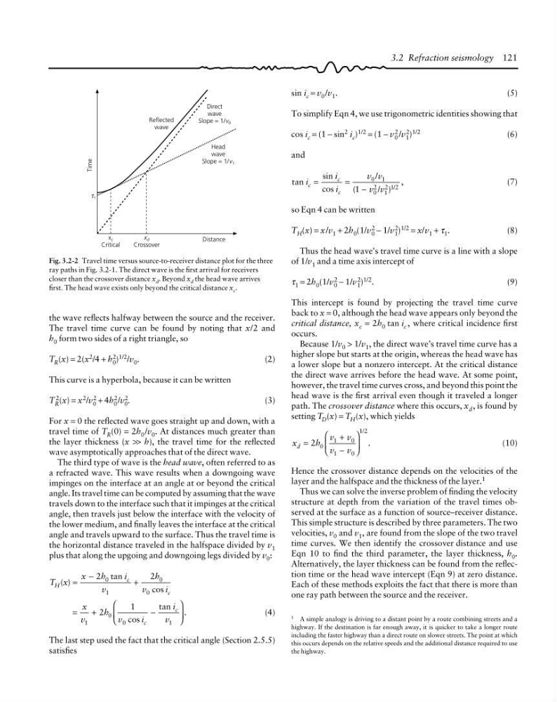
Because 1/v 0 > 1/v 1 , the direct wave’s travel time curve has a
higher slope but starts at the origin, whereas the head wave has
a lower slope but a nonzero intercept. At the critical distance
the direct wave arrives before the head wave. At some point,
however, the travel time curves cross, and beyond this point the
head wave is the first arrival even though it traveled a longer
path. The crossover distance where this occurs, x d , is found by
setting T D (x) = T H (x), which yields
x
h
v
v
v
v
d =
+
−
⎛
⎝
⎜
⎞
⎠
⎟ .
/
2 0
1
0
1
0
1 2
(10)
Hence the crossover distance depends on the velocities of the
layer and the halfspace and the thickness of the layer. 1
Thus we can solve the inverse problem of finding the velocity
structure at depth from the variation of the travel times observed at the surface as a function of source–receiver distance.
This simple structure is described by three parameters. The two
velocities, v 0 and v 1 , are found from the slope of the two travel
time curves. We then identify the crossover distance and use
Eqn 10 to find the third parameter, the layer thickness, h 0 .
Alternatively, the layer thickness can be found from the reflection time or the head wave intercept (Eqn 9) at zero distance.
Each of these methods exploits the fact that there is more than
one ray path between the source and the receiver.
Fig. 3.2-2 Travel time versus source-to-receiver distance plot for the three
ray paths in Fig. 3.2-1. The direct wave is the first arrival for receivers
closer than the crossover distance x d . Beyond x d the head wave arrives
first. The head wave exists only beyond the critical distance x c .
1 A simple analogy is driving to a distant point by a route combining streets and a
highway. If the destination is far enough away, it is quicker to take a longer route
including the faster highway than a direct route on slower streets. The point at which
this occurs depends on the relative speeds and the additional distance required to use
the highway.
3.2 Refraction seismology 121
the wave reflects halfway between the source and the receiver.
The travel time curve can be found by noting that x/2 and
h 0 form two sides of a right triangle, so
T R (x) = 2(x
2 /4 + h
2
0 )
1/2
/v 0 .
(2)
This curve is a hyperbola, because it can be written
T 2
R (x) = x 2 /v 2
0 + 4h 2
0 /v 2
0 .
(3)
For x = 0 the reflected wave goes straight up and down, with a
travel time of T R (0) = 2h 0 /v 0 . At distances much greater than
the layer thickness (x >> h), the travel time for the reflected
wave asymptotically approaches that of the direct wave.
The third type of wave is the head wave, often referred to as
a refracted wave. This wave results when a downgoing wave
impinges on the interface at an angle at or beyond the critical
angle. Its travel time can be computed by assuming that the wave
travels down to the interface such that it impinges at the critical
angle, then travels just below the interface with the velocity of
the lower medium, and finally leaves the interface at the critical
angle and travels upward to the surface. Thus the travel time is
the horizontal distance traveled in the halfspace divided by v 1
plus that along the upgoing and downgoing legs divided by v 0 :
T x
x
h
i
v
h
v
i
H
c
c
( )
tan
cos
=
−
+
2
2
0
1
0
0
x
v
h
v
i
i
v
c
c
cos
tan
.
=
+
−
⎛
⎝
⎜
⎞
⎠
⎟
2
1
1
0
0
1
(4)
The last step used the fact that the critical angle (Section 2.5.5)
satisfies
Direct
wave
Slope = 1/v 0
x d
Crossover
x c
Critical
Distance
Reflected
wave
Head
wave
Slope = 1/v 1
τ 1
sin i c = v 0 /v 1 .
(5)
To simplify Eqn 4, we use trigonometric identities showing that
cos i c = (1 − sin
2 i c )
1/2
= (1 − v
2
0 /v
2
1 )
1/2
(6)
and
tan
sin
cos
/
(
/ )
,
/
i
i
i
v v
v v
c
c
c
=
= −
0 1
0
2
1
2 1 2
1
(7)
so Eqn 4 can be written
T H (x) = x/v 1 + 2h 0 (1/v 2
0 − 1/v 2
1 ) 1/2 = x/v 1 + τ 1 .
(8)
Thus the head wave’s travel time curve is a line with a slope
of 1/v 1 and a time axis intercept of
τ 1 = 2h 0 (1/v 2
0 − 1/v 2
1 ) 1/2 .
(9)
This intercept is found by projecting the travel time curve
back to x = 0, although the head wave appears only beyond the
critical distance, x c = 2h 0 tan i c , where critical incidence first
occurs.
Because 1/v 0 > 1/v 1 , the direct wave’s travel time curve has a
higher slope but starts at the origin, whereas the head wave has
a lower slope but a nonzero intercept. At the critical distance
the direct wave arrives before the head wave. At some point,
however, the travel time curves cross, and beyond this point the
head wave is the first arrival even though it traveled a longer
path. The crossover distance where this occurs, x d , is found by
setting T D (x) = T H (x), which yields
x
h
v
v
v
v
d =
+
−
⎛
⎝
⎜
⎞
⎠
⎟ .
/
2 0
1
0
1
0
1 2
(10)
Hence the crossover distance depends on the velocities of the
layer and the halfspace and the thickness of the layer. 1
Thus we can solve the inverse problem of finding the velocity
structure at depth from the variation of the travel times observed at the surface as a function of source–receiver distance.
This simple structure is described by three parameters. The two
velocities, v 0 and v 1 , are found from the slope of the two travel
time curves. We then identify the crossover distance and use
Eqn 10 to find the third parameter, the layer thickness, h 0 .
Alternatively, the layer thickness can be found from the reflection time or the head wave intercept (Eqn 9) at zero distance.
Each of these methods exploits the fact that there is more than
one ray path between the source and the receiver.
Fig. 3.2-2 Travel time versus source-to-receiver distance plot for the three
ray paths in Fig. 3.2-1. The direct wave is the first arrival for receivers
closer than the crossover distance x d . Beyond x d the head wave arrives
first. The head wave exists only beyond the critical distance x c .
1 A simple analogy is driving to a distant point by a route combining streets and a
highway. If the destination is far enough away, it is quicker to take a longer route
including the faster highway than a direct route on slower streets. The point at which
this occurs depends on the relative speeds and the additional distance required to use
the highway.
3.2 Refraction seismology 121
the wave reflects halfway between the source and the receiver.
The travel time curve can be found by noting that x/2 and
h 0 form two sides of a right triangle, so
T R (x) = 2(x
2 /4 + h
2
0 )
1/2
/v 0 .
(2)
This curve is a hyperbola, because it can be written
T 2
R (x) = x 2 /v 2
0 + 4h 2
0 /v 2
0 .
(3)
For x = 0 the reflected wave goes straight up and down, with a
travel time of T R (0) = 2h 0 /v 0 . At distances much greater than
the layer thickness (x >> h), the travel time for the reflected
wave asymptotically approaches that of the direct wave.
The third type of wave is the head wave, often referred to as
a refracted wave. This wave results when a downgoing wave
impinges on the interface at an angle at or beyond the critical
angle. Its travel time can be computed by assuming that the wave
travels down to the interface such that it impinges at the critical
angle, then travels just below the interface with the velocity of
the lower medium, and finally leaves the interface at the critical
angle and travels upward to the surface. Thus the travel time is
the horizontal distance traveled in the halfspace divided by v 1
plus that along the upgoing and downgoing legs divided by v 0 :
T x
x
h
i
v
h
v
i
H
c
c
( )
tan
cos
=
−
+
2
2
0
1
0
0
x
v
h
v
i
i
v
c
c
cos
tan
.
=
+
−
⎛
⎝
⎜
⎞
⎠
⎟
2
1
1
0
0
1
(4)
The last step used the fact that the critical angle (Section 2.5.5)
satisfies