

height from the ground. The height of the second story is 4 m, the third is 8 m, and
the seventh is 24 m, as indicated in Fig. 12.15. A power generation system based on
effective use of the energy of this drainage water is presented here.
12.4.2.2 Preparation of Experimental Drainage Water Power
Generation System
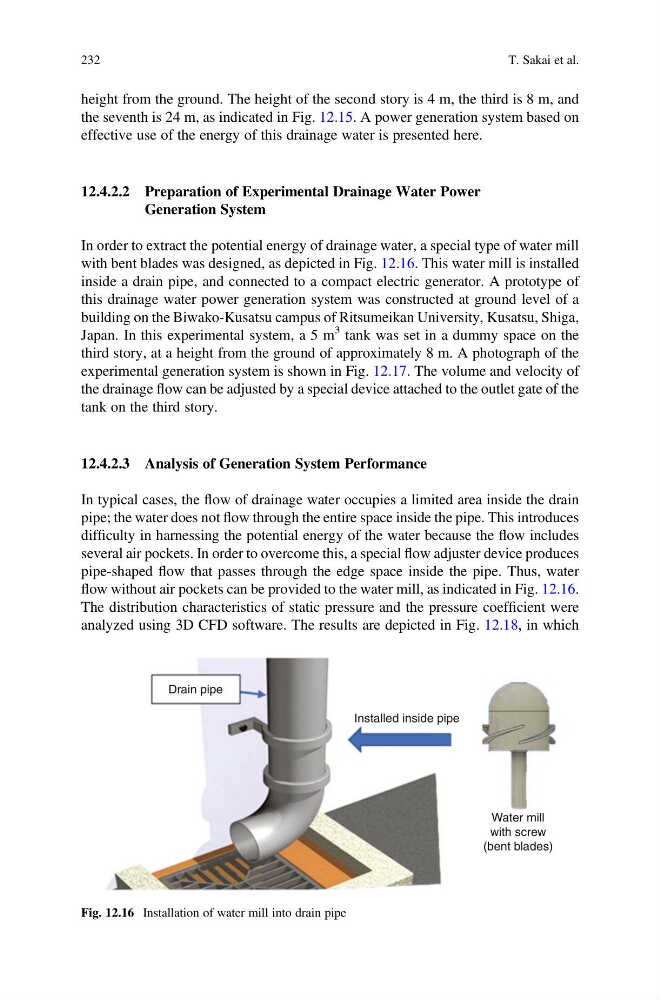
In order to extract the potential energy of drainage water, a special type of water mill
with bent blades was designed, as depicted in Fig. 12.16. This water mill is installed
inside a drain pipe, and connected to a compact electric generator. A prototype of
this drainage water power generation system was constructed at ground level of a
building on the Biwako-Kusatsu campus of Ritsumeikan University, Kusatsu, Shiga,
Japan. In this experimental system, a 5 m
3 tank was set in a dummy space on the
third story, at a height from the ground of approximately 8 m. A photograph of the
experimental generation system is shown in Fig. 12.17. The volume and velocity of
the drainage flow can be adjusted by a special device attached to the outlet gate of the
tank on the third story.
12.4.2.3 Analysis of Generation System Performance
In typical cases, the flow of drainage water occupies a limited area inside the drain
pipe; the water does not flow through the entire space inside the pipe. This introduces
difficulty in harnessing the potential energy of the water because the flow includes
several air pockets. In order to overcome this, a special flow adjuster device produces
pipe-shaped flow that passes through the edge space inside the pipe. Thus, water
flow without air pockets can be provided to the water mill, as indicated in Fig. 12.16.
The distribution characteristics of static pressure and the pressure coefficient were
analyzed using 3D CFD software. The results are depicted in Fig. 12.18, in which
Drain pipe
Installed inside pipe
Water mill
with screw
(bent blades)
Fig. 12.16 Installation of water mill into drain pipe
232
T. Sakai et al.
the seventh is 24 m, as indicated in Fig. 12.15. A power generation system based on
effective use of the energy of this drainage water is presented here.
12.4.2.2 Preparation of Experimental Drainage Water Power
Generation System
In order to extract the potential energy of drainage water, a special type of water mill
with bent blades was designed, as depicted in Fig. 12.16. This water mill is installed
inside a drain pipe, and connected to a compact electric generator. A prototype of
this drainage water power generation system was constructed at ground level of a
building on the Biwako-Kusatsu campus of Ritsumeikan University, Kusatsu, Shiga,
Japan. In this experimental system, a 5 m
3 tank was set in a dummy space on the
third story, at a height from the ground of approximately 8 m. A photograph of the
experimental generation system is shown in Fig. 12.17. The volume and velocity of
the drainage flow can be adjusted by a special device attached to the outlet gate of the
tank on the third story.
12.4.2.3 Analysis of Generation System Performance
In typical cases, the flow of drainage water occupies a limited area inside the drain
pipe; the water does not flow through the entire space inside the pipe. This introduces
difficulty in harnessing the potential energy of the water because the flow includes
several air pockets. In order to overcome this, a special flow adjuster device produces
pipe-shaped flow that passes through the edge space inside the pipe. Thus, water
flow without air pockets can be provided to the water mill, as indicated in Fig. 12.16.
The distribution characteristics of static pressure and the pressure coefficient were
analyzed using 3D CFD software. The results are depicted in Fig. 12.18, in which
Drain pipe
Installed inside pipe
Water mill
with screw
(bent blades)
Fig. 12.16 Installation of water mill into drain pipe
232
T. Sakai et al.