

components like semiconductors, capacitors, and others are mounted. They appear
as single-sided, double-sided, multilayer, and flexible boards. Production of printed
wiring boards can be achieved through three methods: additive, subtractive, or semiadditive technology. However, the subtractive process is the most widely used
method by many manufacturing industries. Furthermore, the actual steps and material use in the manufacturing process depend on the customers’ requirement and
manufacturer’s desires.
Under the board preparation step, insulating layer is introduced in between a twosided-etched copper dielectric boards consisting of fiberglass and epoxy resin, which
are bounded (laminated) together by heat and pressure. Patterns are imaged on the
Table 4.32 (continued)
Toxic organics
Pesticides
Benzo (ghi) perylene
Fluorine
Dibenzo(a,h)anthracene
Indeno(1,2,3-cd)pyrene
Vinyl chloride
Source: [6]
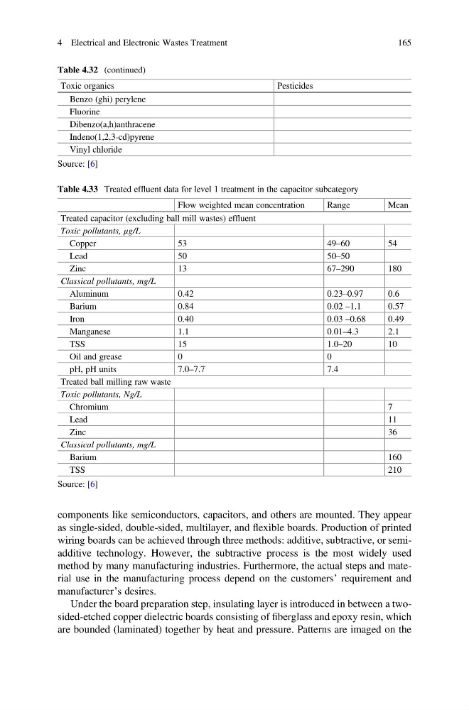
Table 4.33 Treated effluent data for level 1 treatment in the capacitor subcategory
Flow weighted mean concentration
Range
Mean
Treated capacitor (excluding ball mill wastes) effluent
Toxic pollutants, μg/L
Copper
53
49–60
54
Lead
50
50–50
Zinc
13
67–290
180
Classical pollutants, mg/L
Aluminum
0.42
0.23–0.97
0.6
Barium
0.84
0.02 –1.1
0.57
Iron
0.40
0.03 –0.68
0.49
Manganese
1.1
0.01–4.3
2.1
TSS
15
1.0–20
10
Oil and grease
0
0
pH, pH units
7.0–7.7
7.4
Treated ball milling raw waste
Toxic pollutants, Ng/L
Chromium
7
Lead
11
Zinc
36
Classical pollutants, mg/L
Barium
160
TSS
210
Source: [6]
4 Electrical and Electronic Wastes Treatment
165
as single-sided, double-sided, multilayer, and flexible boards. Production of printed
wiring boards can be achieved through three methods: additive, subtractive, or semiadditive technology. However, the subtractive process is the most widely used
method by many manufacturing industries. Furthermore, the actual steps and material use in the manufacturing process depend on the customers’ requirement and
manufacturer’s desires.
Under the board preparation step, insulating layer is introduced in between a twosided-etched copper dielectric boards consisting of fiberglass and epoxy resin, which
are bounded (laminated) together by heat and pressure. Patterns are imaged on the
Table 4.32 (continued)
Toxic organics
Pesticides
Benzo (ghi) perylene
Fluorine
Dibenzo(a,h)anthracene
Indeno(1,2,3-cd)pyrene
Vinyl chloride
Source: [6]
Table 4.33 Treated effluent data for level 1 treatment in the capacitor subcategory
Flow weighted mean concentration
Range
Mean
Treated capacitor (excluding ball mill wastes) effluent
Toxic pollutants, μg/L
Copper
53
49–60
54
Lead
50
50–50
Zinc
13
67–290
180
Classical pollutants, mg/L
Aluminum
0.42
0.23–0.97
0.6
Barium
0.84
0.02 –1.1
0.57
Iron
0.40
0.03 –0.68
0.49
Manganese
1.1
0.01–4.3
2.1
TSS
15
1.0–20
10
Oil and grease
0
0
pH, pH units
7.0–7.7
7.4
Treated ball milling raw waste
Toxic pollutants, Ng/L
Chromium
7
Lead
11
Zinc
36
Classical pollutants, mg/L
Barium
160
TSS
210
Source: [6]
4 Electrical and Electronic Wastes Treatment
165