

polarized light in the crystal indicate that the speed of propagation of the p- and
s-light in this material is different and a phase shift δ between both polarizations
takes place. This effect is known as birefringence.
In some crystals the birefringence effect may be forced. Forced birefringence is
known as a photoelastic effect. A periodic retardation on a beam of linearly polarized
light may be induced by a photoelastic modulator (PEM). In 1979 Hipps and Crosby
proposed the idea of the application of the photoelastic modulation in polarization
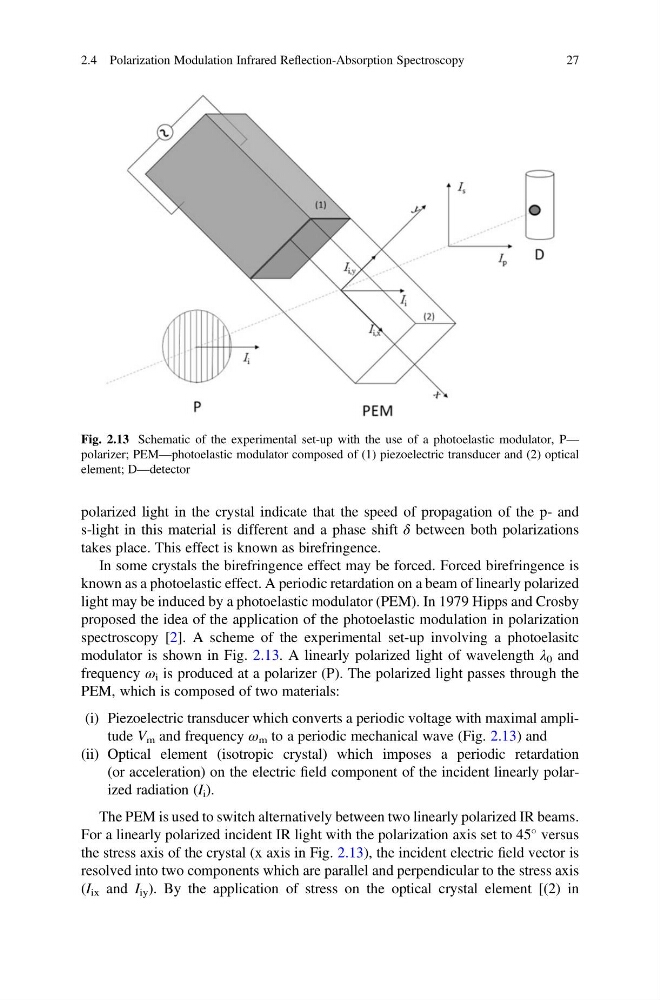
spectroscopy [2]. A scheme of the experimental set-up involving a photoelasitc
modulator is shown in Fig. 2.13. A linearly polarized light of wavelength λ 0 and
frequency ω i is produced at a polarizer (P). The polarized light passes through the
PEM, which is composed of two materials:
(i) Piezoelectric transducer which converts a periodic voltage with maximal amplitude V m and frequency ω m to a periodic mechanical wave (Fig. 2.13) and
(ii) Optical element (isotropic crystal) which imposes a periodic retardation
(or acceleration) on the electric field component of the incident linearly polarized radiation (I i ).
The PEM is used to switch alternatively between two linearly polarized IR beams.
For a linearly polarized incident IR light with the polarization axis set to 45
versus
the stress axis of the crystal (x axis in Fig. 2.13), the incident electric field vector is
resolved into two components which are parallel and perpendicular to the stress axis
(I ix and I iy ). By the application of stress on the optical crystal element [(2) in
Fig. 2.13 Schematic of the experimental set-up with the use of a photoelastic modulator, P—
polarizer; PEM—photoelastic modulator composed of (1) piezoelectric transducer and (2) optical
element; D—detector
2.4 Polarization Modulation Infrared Reflection-Absorption Spectroscopy
27
s-light in this material is different and a phase shift δ between both polarizations
takes place. This effect is known as birefringence.
In some crystals the birefringence effect may be forced. Forced birefringence is
known as a photoelastic effect. A periodic retardation on a beam of linearly polarized
light may be induced by a photoelastic modulator (PEM). In 1979 Hipps and Crosby
proposed the idea of the application of the photoelastic modulation in polarization
spectroscopy [2]. A scheme of the experimental set-up involving a photoelasitc
modulator is shown in Fig. 2.13. A linearly polarized light of wavelength λ 0 and
frequency ω i is produced at a polarizer (P). The polarized light passes through the
PEM, which is composed of two materials:
(i) Piezoelectric transducer which converts a periodic voltage with maximal amplitude V m and frequency ω m to a periodic mechanical wave (Fig. 2.13) and
(ii) Optical element (isotropic crystal) which imposes a periodic retardation
(or acceleration) on the electric field component of the incident linearly polarized radiation (I i ).
The PEM is used to switch alternatively between two linearly polarized IR beams.
For a linearly polarized incident IR light with the polarization axis set to 45
versus
the stress axis of the crystal (x axis in Fig. 2.13), the incident electric field vector is
resolved into two components which are parallel and perpendicular to the stress axis
(I ix and I iy ). By the application of stress on the optical crystal element [(2) in
Fig. 2.13 Schematic of the experimental set-up with the use of a photoelastic modulator, P—
polarizer; PEM—photoelastic modulator composed of (1) piezoelectric transducer and (2) optical
element; D—detector
2.4 Polarization Modulation Infrared Reflection-Absorption Spectroscopy
27