

The Draft Guidance does not specify the locations of the upstream background
monitoring well and the downstream pollution diffusion monitoring well in the
comprehensive disposal site. We refer to the Draft Guidance for the general landfill
site where “the groundwater type is plain pore water, with one boundary perpendicular to the groundwater flow direction or the minimum included angle of less
than 10°”, namely: (1) the upstream background monitoring well is located 30–
50 m upstream of the groundwater flow of the disposal site; (2) the downstream
pollution diffusion monitoring well is located 30–50 m downstream of the
groundwater flow in the disposal site.
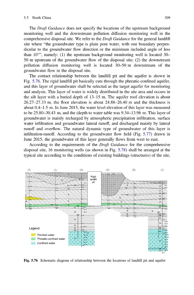
The contact relationship between the landfill pit and the aquifer is shown in
Fig. 5.76. The rigid landfill pit basically cuts through the phreatic-confined aquifer,
and this layer of groundwater shall be selected as the target aquifer for monitoring
and analysis. This layer of water is widely distributed in the site area and occurs in
the silt layer with a buried depth of 13–15 m. The aquifer roof elevation is about
26.27–27.33 m, the floor elevation is about 24.88–26.40 m and the thickness is
about 0.4–1.5 m. In June 2015, the water level elevation of this layer was measured
to be 25.80–30.43 m, and the (depth to water table was 9.34–13.96 m. This layer of
groundwater is mainly recharged by atmospheric precipitation infiltration, surface
water infiltration and groundwater lateral runoff, and discharged mainly by lateral
runoff and overflow. The natural dynamic type of groundwater of this layer is
infiltration-runoff. According to the groundwater flow field (Fig. 5.77) drawn in
June 2015, the groundwater of this layer generally flows from west to east.
According to the requirements of the Draft Guidance for the comprehensive
disposal site, 16 monitoring wells (as shown in Fig. 5.78) shall be arranged at the
typical site according to the conditions of existing buildings (structures) of the site,
Rigid
landfill
pit
Perched water
Confined water
Legend
Phreatic-confined water
Fig. 5.76 Schematic diagram of relationship between the locations of landfill pit and aquifer
5.5 North China
309
monitoring well and the downstream pollution diffusion monitoring well in the
comprehensive disposal site. We refer to the Draft Guidance for the general landfill
site where “the groundwater type is plain pore water, with one boundary perpendicular to the groundwater flow direction or the minimum included angle of less
than 10°”, namely: (1) the upstream background monitoring well is located 30–
50 m upstream of the groundwater flow of the disposal site; (2) the downstream
pollution diffusion monitoring well is located 30–50 m downstream of the
groundwater flow in the disposal site.
The contact relationship between the landfill pit and the aquifer is shown in
Fig. 5.76. The rigid landfill pit basically cuts through the phreatic-confined aquifer,
and this layer of groundwater shall be selected as the target aquifer for monitoring
and analysis. This layer of water is widely distributed in the site area and occurs in
the silt layer with a buried depth of 13–15 m. The aquifer roof elevation is about
26.27–27.33 m, the floor elevation is about 24.88–26.40 m and the thickness is
about 0.4–1.5 m. In June 2015, the water level elevation of this layer was measured
to be 25.80–30.43 m, and the (depth to water table was 9.34–13.96 m. This layer of
groundwater is mainly recharged by atmospheric precipitation infiltration, surface
water infiltration and groundwater lateral runoff, and discharged mainly by lateral
runoff and overflow. The natural dynamic type of groundwater of this layer is
infiltration-runoff. According to the groundwater flow field (Fig. 5.77) drawn in
June 2015, the groundwater of this layer generally flows from west to east.
According to the requirements of the Draft Guidance for the comprehensive
disposal site, 16 monitoring wells (as shown in Fig. 5.78) shall be arranged at the
typical site according to the conditions of existing buildings (structures) of the site,
Rigid
landfill
pit
Perched water
Confined water
Legend
Phreatic-confined water
Fig. 5.76 Schematic diagram of relationship between the locations of landfill pit and aquifer
5.5 North China
309