

432
G. Osada et al.
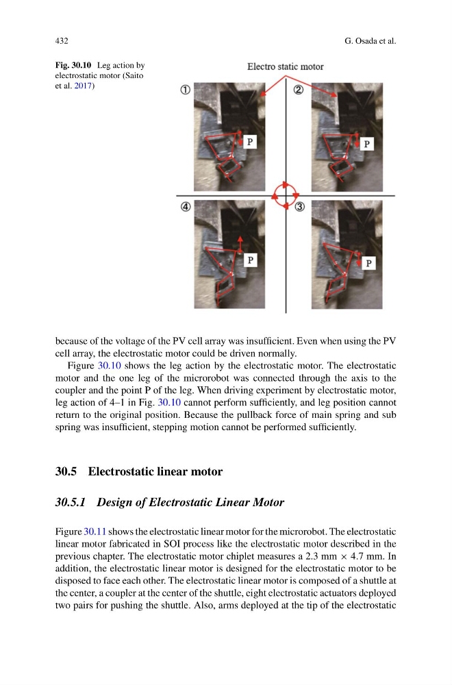
Fig. 30.10 Leg action by
electrostatic motor (Saito
et al. 2017)
because of the voltage of the PV cell array was insufficient. Even when using the PV
cell array, the electrostatic motor could be driven normally.
Figure 30.10 shows the leg action by the electrostatic motor. The electrostatic
motor and the one leg of the microrobot was connected through the axis to the
coupler and the point P of the leg. When driving experiment by electrostatic motor,
leg action of 4–1 in Fig. 30.10 cannot perform sufficiently, and leg position cannot
return to the original position. Because the pullback force of main spring and sub
spring was insufficient, stepping motion cannot be performed sufficiently.
30.5 Electrostatic linear motor
30.5.1 Design of Electrostatic Linear Motor
Figure 30.11 shows the electrostatic linear motor for the microrobot. The electrostatic
linear motor fabricated in SOI process like the electrostatic motor described in the
previous chapter. The electrostatic motor chiplet measures a 2.3 mm × 4.7 mm. In
addition, the electrostatic linear motor is designed for the electrostatic motor to be
disposed to face each other. The electrostatic linear motor is composed of a shuttle at
the center, a coupler at the center of the shuttle, eight electrostatic actuators deployed
two pairs for pushing the shuttle. Also, arms deployed at the tip of the electrostatic
G. Osada et al.
Fig. 30.10 Leg action by
electrostatic motor (Saito
et al. 2017)
because of the voltage of the PV cell array was insufficient. Even when using the PV
cell array, the electrostatic motor could be driven normally.
Figure 30.10 shows the leg action by the electrostatic motor. The electrostatic
motor and the one leg of the microrobot was connected through the axis to the
coupler and the point P of the leg. When driving experiment by electrostatic motor,
leg action of 4–1 in Fig. 30.10 cannot perform sufficiently, and leg position cannot
return to the original position. Because the pullback force of main spring and sub
spring was insufficient, stepping motion cannot be performed sufficiently.
30.5 Electrostatic linear motor
30.5.1 Design of Electrostatic Linear Motor
Figure 30.11 shows the electrostatic linear motor for the microrobot. The electrostatic
linear motor fabricated in SOI process like the electrostatic motor described in the
previous chapter. The electrostatic motor chiplet measures a 2.3 mm × 4.7 mm. In
addition, the electrostatic linear motor is designed for the electrostatic motor to be
disposed to face each other. The electrostatic linear motor is composed of a shuttle at
the center, a coupler at the center of the shuttle, eight electrostatic actuators deployed
two pairs for pushing the shuttle. Also, arms deployed at the tip of the electrostatic