

30 Development of Electrostatic Linear Motor for Insect-Type …
429
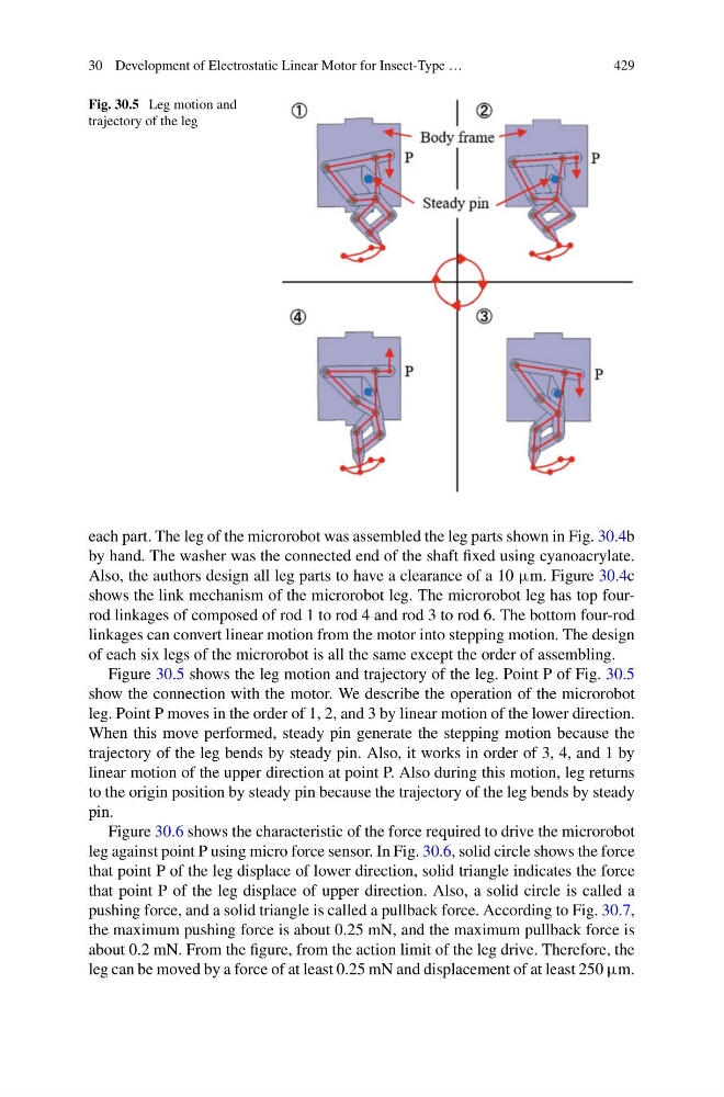
Fig. 30.5 Leg motion and
trajectory of the leg
each part. The leg of the microrobot was assembled the leg parts shown in Fig. 30.4b
by hand. The washer was the connected end of the shaft fixed using cyanoacrylate.
Also, the authors design all leg parts to have a clearance of a 10 µm. Figure 30.4c
shows the link mechanism of the microrobot leg. The microrobot leg has top fourrod linkages of composed of rod 1 to rod 4 and rod 3 to rod 6. The bottom four-rod
linkages can convert linear motion from the motor into stepping motion. The design
of each six legs of the microrobot is all the same except the order of assembling.
Figure 30.5 shows the leg motion and trajectory of the leg. Point P of Fig. 30.5
show the connection with the motor. We describe the operation of the microrobot
leg. Point P moves in the order of 1, 2, and 3 by linear motion of the lower direction.
When this move performed, steady pin generate the stepping motion because the
trajectory of the leg bends by steady pin. Also, it works in order of 3, 4, and 1 by
linear motion of the upper direction at point P. Also during this motion, leg returns
to the origin position by steady pin because the trajectory of the leg bends by steady
pin.
Figure 30.6 shows the characteristic of the force required to drive the microrobot
leg against point P using micro force sensor. In Fig. 30.6, solid circle shows the force
that point P of the leg displace of lower direction, solid triangle indicates the force
that point P of the leg displace of upper direction. Also, a solid circle is called a
pushing force, and a solid triangle is called a pullback force. According to Fig. 30.7,
the maximum pushing force is about 0.25 mN, and the maximum pullback force is
about 0.2 mN. From the figure, from the action limit of the leg drive. Therefore, the
leg can be moved by a force of at least 0.25 mN and displacement of at least 250 µm.
429
Fig. 30.5 Leg motion and
trajectory of the leg
each part. The leg of the microrobot was assembled the leg parts shown in Fig. 30.4b
by hand. The washer was the connected end of the shaft fixed using cyanoacrylate.
Also, the authors design all leg parts to have a clearance of a 10 µm. Figure 30.4c
shows the link mechanism of the microrobot leg. The microrobot leg has top fourrod linkages of composed of rod 1 to rod 4 and rod 3 to rod 6. The bottom four-rod
linkages can convert linear motion from the motor into stepping motion. The design
of each six legs of the microrobot is all the same except the order of assembling.
Figure 30.5 shows the leg motion and trajectory of the leg. Point P of Fig. 30.5
show the connection with the motor. We describe the operation of the microrobot
leg. Point P moves in the order of 1, 2, and 3 by linear motion of the lower direction.
When this move performed, steady pin generate the stepping motion because the
trajectory of the leg bends by steady pin. Also, it works in order of 3, 4, and 1 by
linear motion of the upper direction at point P. Also during this motion, leg returns
to the origin position by steady pin because the trajectory of the leg bends by steady
pin.
Figure 30.6 shows the characteristic of the force required to drive the microrobot
leg against point P using micro force sensor. In Fig. 30.6, solid circle shows the force
that point P of the leg displace of lower direction, solid triangle indicates the force
that point P of the leg displace of upper direction. Also, a solid circle is called a
pushing force, and a solid triangle is called a pullback force. According to Fig. 30.7,
the maximum pushing force is about 0.25 mN, and the maximum pullback force is
about 0.2 mN. From the figure, from the action limit of the leg drive. Therefore, the
leg can be moved by a force of at least 0.25 mN and displacement of at least 250 µm.