

20 Part Agents for Exchanging Modules of Manipulators
291
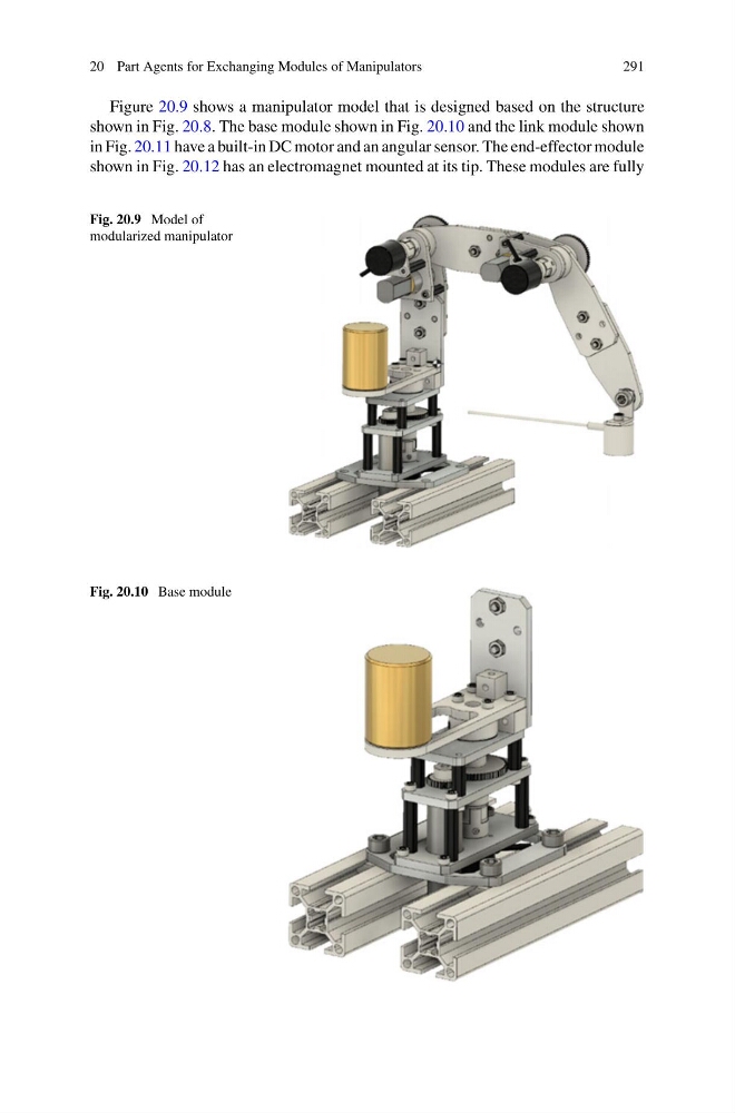
Figure 20.9 shows a manipulator model that is designed based on the structure
shown in Fig. 20.8. The base module shown in Fig. 20.10 and the link module shown
in Fig. 20.11 have a built-in DC motor and an angular sensor. The end-effector module
shown in Fig. 20.12 has an electromagnet mounted at its tip. These modules are fully
Fig. 20.9 Model of
modularized manipulator
Fig. 20.10 Base module
291
Figure 20.9 shows a manipulator model that is designed based on the structure
shown in Fig. 20.8. The base module shown in Fig. 20.10 and the link module shown
in Fig. 20.11 have a built-in DC motor and an angular sensor. The end-effector module
shown in Fig. 20.12 has an electromagnet mounted at its tip. These modules are fully
Fig. 20.9 Model of
modularized manipulator
Fig. 20.10 Base module