

2.2 Experimental Methods
53
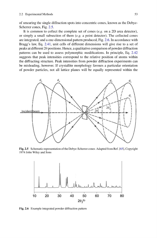
of smearing the single diffraction spots into concentric cones, known as the DebyeScherrer cones, Fig. 2.5.
It is common to collect the complete set of cones (e.g. on a 2D area detector),
or simply a small subsection of them (e.g. a point detector). The collected cones
are integrated, and a one-dimensional pattern produced, Fig. 2.6. In accordance with
Bragg’s law, Eq. 2.41, unit cells of different dimensions will give rise to a set of
peaks at different 2θ positions. Hence, a qualitative comparison of powder diffraction
patterns can be used to assess polymorphic modifications. In principle, Eq. 2.42
suggests that peak intensities correspond to the relative position of atoms within
the diffracting structure. Peak intensities from powder diffraction experiments can
be misleading, however. If crystallite morphology favours a particular orientation
of powder particles, not all lattice planes will be equally represented within the
Fig. 2.5 Schematic representation of the Debye-Scherrer cones Adapted from Ref. [65], Copyright
1974 John Wiley and Sons
Fig. 2.6 Example integrated powder diffraction pattern
53
of smearing the single diffraction spots into concentric cones, known as the DebyeScherrer cones, Fig. 2.5.
It is common to collect the complete set of cones (e.g. on a 2D area detector),
or simply a small subsection of them (e.g. a point detector). The collected cones
are integrated, and a one-dimensional pattern produced, Fig. 2.6. In accordance with
Bragg’s law, Eq. 2.41, unit cells of different dimensions will give rise to a set of
peaks at different 2θ positions. Hence, a qualitative comparison of powder diffraction
patterns can be used to assess polymorphic modifications. In principle, Eq. 2.42
suggests that peak intensities correspond to the relative position of atoms within
the diffracting structure. Peak intensities from powder diffraction experiments can
be misleading, however. If crystallite morphology favours a particular orientation
of powder particles, not all lattice planes will be equally represented within the
Fig. 2.5 Schematic representation of the Debye-Scherrer cones Adapted from Ref. [65], Copyright
1974 John Wiley and Sons
Fig. 2.6 Example integrated powder diffraction pattern