

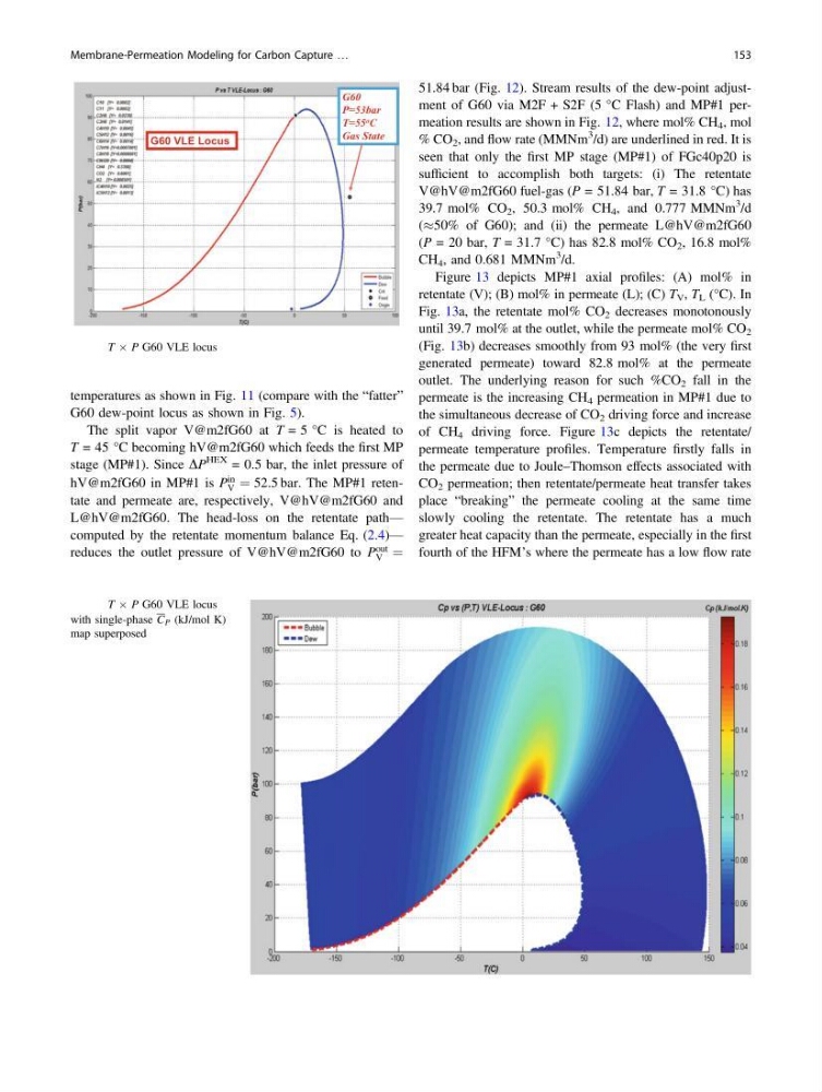
temperatures as shown in Fig. 11 (compare with the “fatter”
G60 dew-point locus as shown in Fig. 5).
The split vapor V@m2fG60 at T = 5 °C is heated to
T = 45 °C becoming hV@m2fG60 which feeds the first MP
stage (MP#1). Since DP
HEX = 0.5 bar, the inlet pressure of
hV@m2fG60 in MP#1 is P
in
V ¼ 52.5 bar. The MP#1 retentate and permeate are, respectively, V@hV@m2fG60 and
L@hV@m2fG60. The head-loss on the retentate path—
computed by the retentate momentum balance Eq. (2.4)—
reduces the outlet pressure of V@hV@m2fG60 to P
out
V ¼
51.84 bar (Fig. 12). Stream results of the dew-point adjustment of G60 via M2F + S2F (5 °C Flash) and MP#1 permeation results are shown in Fig. 12, where mol% CH 4 , mol
% CO 2 , and flow rate (MMNm
3 /d) are underlined in red. It is
seen that only the first MP stage (MP#1) of FGc40p20 is
sufficient to accomplish both targets: (i) The retentate
V@hV@m2fG60 fuel-gas (P = 51.84 bar, T = 31.8 °C) has
39.7 mol% CO 2 , 50.3 mol% CH 4 , and 0.777 MMNm
3 /d
(%50% of G60); and (ii) the permeate L@hV@m2fG60
(P = 20 bar, T = 31.7 °C) has 82.8 mol% CO 2 , 16.8 mol%
CH 4 , and 0.681 MMNm
3 /d.
Figure 13 depicts MP#1 axial profiles: (A) mol% in
retentate (V); (B) mol% in permeate (L); (C) T V , T L (°C). In
Fig. 13a, the retentate mol% CO 2 decreases monotonously
until 39.7 mol% at the outlet, while the permeate mol% CO 2
(Fig. 13b) decreases smoothly from 93 mol% (the very first
generated permeate) toward 82.8 mol% at the permeate
outlet. The underlying reason for such %CO 2 fall in the
permeate is the increasing CH 4 permeation in MP#1 due to
the simultaneous decrease of CO 2 driving force and increase
of CH 4 driving force. Figure 13c depicts the retentate/
permeate temperature profiles. Temperature firstly falls in
the permeate due to Joule–Thomson effects associated with
CO 2 permeation; then retentate/permeate heat transfer takes
place “breaking” the permeate cooling at the same time
slowly cooling the retentate. The retentate has a much
greater heat capacity than the permeate, especially in the first
fourth of the HFM’s where the permeate has a low flow rate
G60 VLE Locus
G60
P=53bar
T=55 o C
Gas State
Fig. 5 T Â P G60 VLE locus
Fig. 6 T Â P G60 VLE locus
with single-phase C P (kJ/mol K)
map superposed
Membrane-Permeation Modeling for Carbon Capture …
153
G60 dew-point locus as shown in Fig. 5).
The split vapor V@m2fG60 at T = 5 °C is heated to
T = 45 °C becoming hV@m2fG60 which feeds the first MP
stage (MP#1). Since DP
HEX = 0.5 bar, the inlet pressure of
hV@m2fG60 in MP#1 is P
in
V ¼ 52.5 bar. The MP#1 retentate and permeate are, respectively, V@hV@m2fG60 and
L@hV@m2fG60. The head-loss on the retentate path—
computed by the retentate momentum balance Eq. (2.4)—
reduces the outlet pressure of V@hV@m2fG60 to P
out
V ¼
51.84 bar (Fig. 12). Stream results of the dew-point adjustment of G60 via M2F + S2F (5 °C Flash) and MP#1 permeation results are shown in Fig. 12, where mol% CH 4 , mol
% CO 2 , and flow rate (MMNm
3 /d) are underlined in red. It is
seen that only the first MP stage (MP#1) of FGc40p20 is
sufficient to accomplish both targets: (i) The retentate
V@hV@m2fG60 fuel-gas (P = 51.84 bar, T = 31.8 °C) has
39.7 mol% CO 2 , 50.3 mol% CH 4 , and 0.777 MMNm
3 /d
(%50% of G60); and (ii) the permeate L@hV@m2fG60
(P = 20 bar, T = 31.7 °C) has 82.8 mol% CO 2 , 16.8 mol%
CH 4 , and 0.681 MMNm
3 /d.
Figure 13 depicts MP#1 axial profiles: (A) mol% in
retentate (V); (B) mol% in permeate (L); (C) T V , T L (°C). In
Fig. 13a, the retentate mol% CO 2 decreases monotonously
until 39.7 mol% at the outlet, while the permeate mol% CO 2
(Fig. 13b) decreases smoothly from 93 mol% (the very first
generated permeate) toward 82.8 mol% at the permeate
outlet. The underlying reason for such %CO 2 fall in the
permeate is the increasing CH 4 permeation in MP#1 due to
the simultaneous decrease of CO 2 driving force and increase
of CH 4 driving force. Figure 13c depicts the retentate/
permeate temperature profiles. Temperature firstly falls in
the permeate due to Joule–Thomson effects associated with
CO 2 permeation; then retentate/permeate heat transfer takes
place “breaking” the permeate cooling at the same time
slowly cooling the retentate. The retentate has a much
greater heat capacity than the permeate, especially in the first
fourth of the HFM’s where the permeate has a low flow rate
G60 VLE Locus
G60
P=53bar
T=55 o C
Gas State
Fig. 5 T Â P G60 VLE locus
Fig. 6 T Â P G60 VLE locus
with single-phase C P (kJ/mol K)
map superposed
Membrane-Permeation Modeling for Carbon Capture …
153