

balances are written for retentate and permeate streams in
Eqs. (2.4) and (2.5) in order to express momentum changes
as temperature and pressure effects. In the same way, temperature and pressure effects are written as consequences of
energy changes of retentate and permeate in the 1D energy
balance relationships Eqs. (2.6) and (2.7). Retentate/
permeate momentum changes derive from velocity changes, gravity force, and shear stress, while retentate/permeate
energy changes result from velocity changes, gravity work,
shear stress work, trans-membrane mass/energy transfers,
and heat transfers (permeate/retentate and retentate-outside).
Equations (2.2) to (2.7) represent a system of 2nc + 4
nonlinear ordinary differential equations (ODE) with one
independent variable (z) for 2nc + 4 dependent variables of
the HFM model; namely, temperature, pressure, and species
molar flow rates of retentate and permeate; i.e., T V , T L , P V ,
P L , V k (k = 1…nc), and L k (k = 1…nc).
Equations (2.1) and (2.8) to (2.21) represent subsidiary
relationships for calculating terms within the set of 2nc + 4
ODE’s. For example, the retentate/permeate shear stresses at
contact surfaces are shown in Eqs. (2.10) and (2.11),
respectively, where the respective dimensionless Darcy
friction factors (f V ; f L ) are predicted by the universal formula
of Churchill (1977) using the respective Reynolds numbers
(Re V ; Re L ), the respective surface roughnesses (e V ; e L ) and
the respective hydraulic diameters (D V ; D L ) defined in
Eq. (2.12). Hydraulic diameters and Reynolds numbers of
retentate/permeate are written in terms of the respective flow
perimeters (} V ; } L ) defined in Eq. (2.13). Retentate/
permeate dynamic viscosities (l V ; l L ) for the Reynolds
numbers (Re V ; Re L ) are estimated via the correlation of
Chung et al. (1988) for multicomponent gases at
high-pressure as shown in Eq. (2.14).
Mass flow rates (kg/s) of retentate and permeate (q V ; q L )
are shown in Eq. (2.15), while Eq. (2.16) expresses the total
trans-membrane mass flux q TM (kg s
−1 m
−2 ).
Partial molar energy of kth species in retentate and permeate (E
V
k ; E
L
k ) include kth species partial molar enthalpy
and partial molar kinetic and potential energies as given in
Eqs. (2.8) and (2.9). Density differential coefficients with (T,
P) are written in Eq. (2.17) for permeate and retentate.
Retentate (V) and permeate (L) partial molar enthalpies of
kth species, molar heat capacities at constant pressure, densities, and species fugacities are, respectively, given in Eqs.
(2.18), (2.19), (2.20), and (2.21). Thermodynamic properties
in Eqs. (2.1)–(2.16) were isolated in Eqs. (2.17)–(2.21) with
the respective dependencies on the model dependent variables. They are calculated directly (e.g., q V ; q L ) from an
appropriate equation of state (EOS) for high-pressure CO 2 -
rich NG such as the Peng–Robinson EOS (PR-EOS), or
from a two-step procedure using ideal gas properties [e.g.,
kth species ideal gas enthalpy H
0
k ðTÞ and stream ideal gas
enthalpy H
0 ðTÞ] and the corresponding correcting residual
properties [e.g., H
R
V ðT V ; P V ; VÞ ; H
R
L ðT L ; P L ; LÞ] calculated
with PR-EOS.
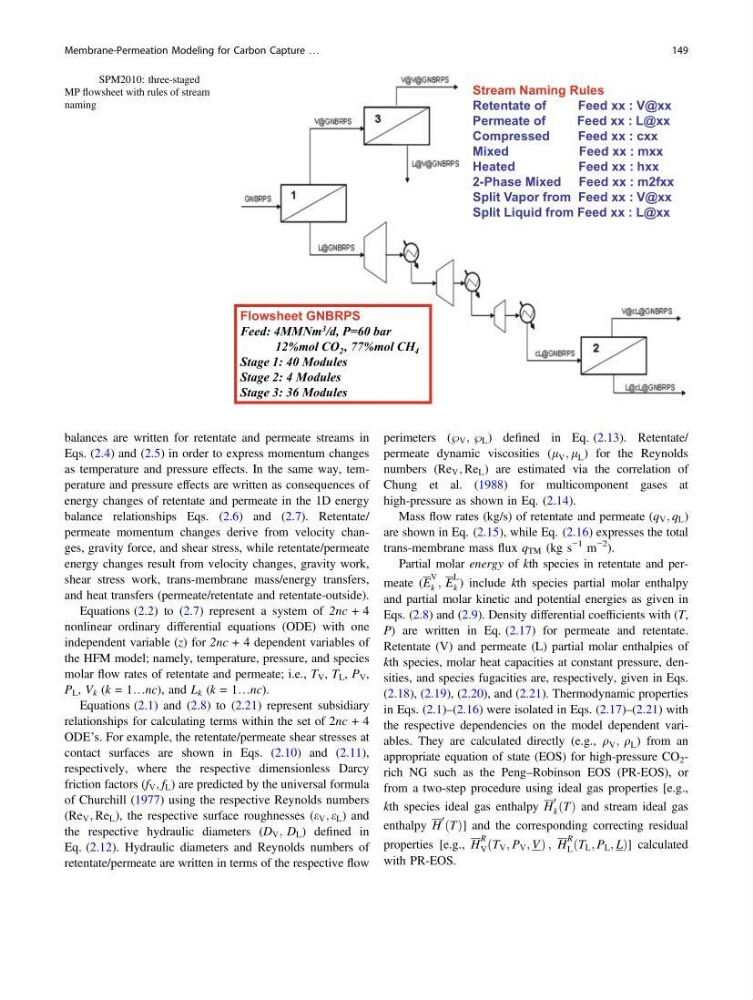
Stream Naming Rules
Retentate of
Feed xx : V@xx
Permeate of
Feed xx : L@xx
Compressed
Feed xx : cxx
Mixed
Feed xx : mxx
Heated
Feed xx : hxx
2-Phase Mixed Feed xx : m2fxx
Split Vapor from Feed xx : V@xx
Split Liquid from Feed xx : L@xx
Flowsheet GNBRPS
Feed: 4MMNm 3 /d, P=60 bar
12%mol CO 2 , 77%mol CH 4
Stage 1: 40 Modules
Stage 2: 4 Modules
Stage 3: 36 Modules
Fig. 4 SPM2010: three-staged
MP flowsheet with rules of stream
naming
Membrane-Permeation Modeling for Carbon Capture …
149
Eqs. (2.4) and (2.5) in order to express momentum changes
as temperature and pressure effects. In the same way, temperature and pressure effects are written as consequences of
energy changes of retentate and permeate in the 1D energy
balance relationships Eqs. (2.6) and (2.7). Retentate/
permeate momentum changes derive from velocity changes, gravity force, and shear stress, while retentate/permeate
energy changes result from velocity changes, gravity work,
shear stress work, trans-membrane mass/energy transfers,
and heat transfers (permeate/retentate and retentate-outside).
Equations (2.2) to (2.7) represent a system of 2nc + 4
nonlinear ordinary differential equations (ODE) with one
independent variable (z) for 2nc + 4 dependent variables of
the HFM model; namely, temperature, pressure, and species
molar flow rates of retentate and permeate; i.e., T V , T L , P V ,
P L , V k (k = 1…nc), and L k (k = 1…nc).
Equations (2.1) and (2.8) to (2.21) represent subsidiary
relationships for calculating terms within the set of 2nc + 4
ODE’s. For example, the retentate/permeate shear stresses at
contact surfaces are shown in Eqs. (2.10) and (2.11),
respectively, where the respective dimensionless Darcy
friction factors (f V ; f L ) are predicted by the universal formula
of Churchill (1977) using the respective Reynolds numbers
(Re V ; Re L ), the respective surface roughnesses (e V ; e L ) and
the respective hydraulic diameters (D V ; D L ) defined in
Eq. (2.12). Hydraulic diameters and Reynolds numbers of
retentate/permeate are written in terms of the respective flow
perimeters (} V ; } L ) defined in Eq. (2.13). Retentate/
permeate dynamic viscosities (l V ; l L ) for the Reynolds
numbers (Re V ; Re L ) are estimated via the correlation of
Chung et al. (1988) for multicomponent gases at
high-pressure as shown in Eq. (2.14).
Mass flow rates (kg/s) of retentate and permeate (q V ; q L )
are shown in Eq. (2.15), while Eq. (2.16) expresses the total
trans-membrane mass flux q TM (kg s
−1 m
−2 ).
Partial molar energy of kth species in retentate and permeate (E
V
k ; E
L
k ) include kth species partial molar enthalpy
and partial molar kinetic and potential energies as given in
Eqs. (2.8) and (2.9). Density differential coefficients with (T,
P) are written in Eq. (2.17) for permeate and retentate.
Retentate (V) and permeate (L) partial molar enthalpies of
kth species, molar heat capacities at constant pressure, densities, and species fugacities are, respectively, given in Eqs.
(2.18), (2.19), (2.20), and (2.21). Thermodynamic properties
in Eqs. (2.1)–(2.16) were isolated in Eqs. (2.17)–(2.21) with
the respective dependencies on the model dependent variables. They are calculated directly (e.g., q V ; q L ) from an
appropriate equation of state (EOS) for high-pressure CO 2 -
rich NG such as the Peng–Robinson EOS (PR-EOS), or
from a two-step procedure using ideal gas properties [e.g.,
kth species ideal gas enthalpy H
0
k ðTÞ and stream ideal gas
enthalpy H
0 ðTÞ] and the corresponding correcting residual
properties [e.g., H
R
V ðT V ; P V ; VÞ ; H
R
L ðT L ; P L ; LÞ] calculated
with PR-EOS.
Stream Naming Rules
Retentate of
Feed xx : V@xx
Permeate of
Feed xx : L@xx
Compressed
Feed xx : cxx
Mixed
Feed xx : mxx
Heated
Feed xx : hxx
2-Phase Mixed Feed xx : m2fxx
Split Vapor from Feed xx : V@xx
Split Liquid from Feed xx : L@xx
Flowsheet GNBRPS
Feed: 4MMNm 3 /d, P=60 bar
12%mol CO 2 , 77%mol CH 4
Stage 1: 40 Modules
Stage 2: 4 Modules
Stage 3: 36 Modules
Fig. 4 SPM2010: three-staged
MP flowsheet with rules of stream
naming
Membrane-Permeation Modeling for Carbon Capture …
149