

direction. Typically, h can vary from 0° to 90°, but 90° is
preferable to prevent too much contact between HFM and
plausible condensates forming in the high-pressure retentate
side. All MP modules are also supposed to have same
geometry, same number of HFM filaments, same HFM
characteristics, same permeate discharge pressure, and same
gas feed (composition, flow rate, temperature, and pressure).
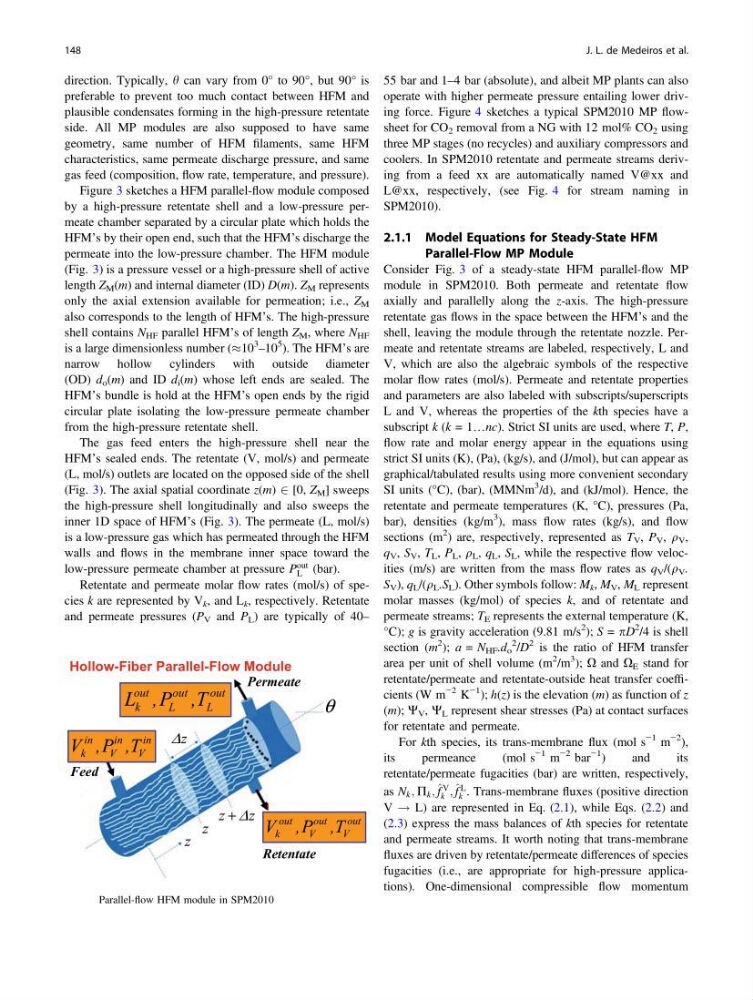
Figure 3 sketches a HFM parallel-flow module composed
by a high-pressure retentate shell and a low-pressure permeate chamber separated by a circular plate which holds the
HFM’s by their open end, such that the HFM’s discharge the
permeate into the low-pressure chamber. The HFM module
(Fig. 3) is a pressure vessel or a high-pressure shell of active
length Z M (m) and internal diameter (ID) D(m). Z M represents
only the axial extension available for permeation; i.e., Z M
also corresponds to the length of HFM’s. The high-pressure
shell contains N HF parallel HFM’s of length Z M , where N HF
is a large dimensionless number (%10
3
–10
5 ). The HFM’s are
narrow hollow cylinders with outside diameter
(OD) d o (m) and ID d i (m) whose left ends are sealed. The
HFM’s bundle is hold at the HFM’s open ends by the rigid
circular plate isolating the low-pressure permeate chamber
from the high-pressure retentate shell.
The gas feed enters the high-pressure shell near the
HFM’s sealed ends. The retentate (V, mol/s) and permeate
(L, mol/s) outlets are located on the opposed side of the shell
(Fig. 3). The axial spatial coordinate z(m) 2 [0, Z M ] sweeps
the high-pressure shell longitudinally and also sweeps the
inner 1D space of HFM’s (Fig. 3). The permeate (L, mol/s)
is a low-pressure gas which has permeated through the HFM
walls and flows in the membrane inner space toward the
low-pressure permeate chamber at pressure P
out
L (bar).
Retentate and permeate molar flow rates (mol/s) of species k are represented by V k , and L k , respectively. Retentate
and permeate pressures (P V and P L ) are typically of 40–
55 bar and 1–4 bar (absolute), and albeit MP plants can also
operate with higher permeate pressure entailing lower driving force. Figure 4 sketches a typical SPM2010 MP flowsheet for CO 2 removal from a NG with 12 mol% CO 2 using
three MP stages (no recycles) and auxiliary compressors and
coolers. In SPM2010 retentate and permeate streams deriving from a feed xx are automatically named V@xx and
L@xx, respectively, (see Fig. 4 for stream naming in
SPM2010).
2.1.1 Model Equations for Steady-State HFM
Parallel-Flow MP Module
Consider Fig. 3 of a steady-state HFM parallel-flow MP
module in SPM2010. Both permeate and retentate flow
axially and parallelly along the z-axis. The high-pressure
retentate gas flows in the space between the HFM’s and the
shell, leaving the module through the retentate nozzle. Permeate and retentate streams are labeled, respectively, L and
V, which are also the algebraic symbols of the respective
molar flow rates (mol/s). Permeate and retentate properties
and parameters are also labeled with subscripts/superscripts
L and V, whereas the properties of the kth species have a
subscript k (k = 1…nc). Strict SI units are used, where T, P,
flow rate and molar energy appear in the equations using
strict SI units (K), (Pa), (kg/s), and (J/mol), but can appear as
graphical/tabulated results using more convenient secondary
SI units (°C), (bar), (MMNm
3 /d), and (kJ/mol). Hence, the
retentate and permeate temperatures (K, °C), pressures (Pa,
bar), densities (kg/m
3 ), mass flow rates (kg/s), and flow
sections (m
2 ) are, respectively, represented as T V , P V , q V ,
q V , S V , T L , P L , q L , q L , S L , while the respective flow velocities (m/s) are written from the mass flow rates as q V /(q V .
S V ), q L /(q L .S L ). Other symbols follow: M k , M V , M L represent
molar masses (kg/mol) of species k, and of retentate and
permeate streams; T E represents the external temperature (K,
°C); g is gravity acceleration (9.81 m/s
2 ); S = pD
2 /4 is shell
section (m
2 ); a = N HF .d o
2 /D
2 is the ratio of HFM transfer
area per unit of shell volume (m
2 /m
3 ); X and X E stand for
retentate/permeate and retentate-outside heat transfer coefficients (W m
−2 K
−1 ); h(z) is the elevation (m) as function of z
(m); W V , W L represent shear stresses (Pa) at contact surfaces
for retentate and permeate.
For kth species, its trans-membrane flux (mol s
−1 m
−2 ),
its
permeance
(mol s
−1 m
−2 bar
−1 )
and
its
retentate/permeate fugacities (bar) are written, respectively,
as N k ; P k ; ^ f
V
k ; ^ f
L
k . Trans-membrane fluxes (positive direction
V ! L) are represented in Eq. (2.1), while Eqs. (2.2) and
(2.3) express the mass balances of kth species for retentate
and permeate streams. It worth noting that trans-membrane
fluxes are driven by retentate/permeate differences of species
fugacities (i.e., are appropriate for high-pressure applications). One-dimensional compressible flow momentum
Hollow-Fiber Parallel-Flow Module
Retentate
out
out
out
k
V
V
V ,P ,T
in
in
in
k
V
V
V ,P ,T
Feed
out
out
out
k
L
L
L ,P ,T
θ
z
z
Δ
+
Permeate
z
z
z
Δ
Fig. 3 Parallel-flow HFM module in SPM2010
148
J. L. de Medeiros et al.
preferable to prevent too much contact between HFM and
plausible condensates forming in the high-pressure retentate
side. All MP modules are also supposed to have same
geometry, same number of HFM filaments, same HFM
characteristics, same permeate discharge pressure, and same
gas feed (composition, flow rate, temperature, and pressure).
Figure 3 sketches a HFM parallel-flow module composed
by a high-pressure retentate shell and a low-pressure permeate chamber separated by a circular plate which holds the
HFM’s by their open end, such that the HFM’s discharge the
permeate into the low-pressure chamber. The HFM module
(Fig. 3) is a pressure vessel or a high-pressure shell of active
length Z M (m) and internal diameter (ID) D(m). Z M represents
only the axial extension available for permeation; i.e., Z M
also corresponds to the length of HFM’s. The high-pressure
shell contains N HF parallel HFM’s of length Z M , where N HF
is a large dimensionless number (%10
3
–10
5 ). The HFM’s are
narrow hollow cylinders with outside diameter
(OD) d o (m) and ID d i (m) whose left ends are sealed. The
HFM’s bundle is hold at the HFM’s open ends by the rigid
circular plate isolating the low-pressure permeate chamber
from the high-pressure retentate shell.
The gas feed enters the high-pressure shell near the
HFM’s sealed ends. The retentate (V, mol/s) and permeate
(L, mol/s) outlets are located on the opposed side of the shell
(Fig. 3). The axial spatial coordinate z(m) 2 [0, Z M ] sweeps
the high-pressure shell longitudinally and also sweeps the
inner 1D space of HFM’s (Fig. 3). The permeate (L, mol/s)
is a low-pressure gas which has permeated through the HFM
walls and flows in the membrane inner space toward the
low-pressure permeate chamber at pressure P
out
L (bar).
Retentate and permeate molar flow rates (mol/s) of species k are represented by V k , and L k , respectively. Retentate
and permeate pressures (P V and P L ) are typically of 40–
55 bar and 1–4 bar (absolute), and albeit MP plants can also
operate with higher permeate pressure entailing lower driving force. Figure 4 sketches a typical SPM2010 MP flowsheet for CO 2 removal from a NG with 12 mol% CO 2 using
three MP stages (no recycles) and auxiliary compressors and
coolers. In SPM2010 retentate and permeate streams deriving from a feed xx are automatically named V@xx and
L@xx, respectively, (see Fig. 4 for stream naming in
SPM2010).
2.1.1 Model Equations for Steady-State HFM
Parallel-Flow MP Module
Consider Fig. 3 of a steady-state HFM parallel-flow MP
module in SPM2010. Both permeate and retentate flow
axially and parallelly along the z-axis. The high-pressure
retentate gas flows in the space between the HFM’s and the
shell, leaving the module through the retentate nozzle. Permeate and retentate streams are labeled, respectively, L and
V, which are also the algebraic symbols of the respective
molar flow rates (mol/s). Permeate and retentate properties
and parameters are also labeled with subscripts/superscripts
L and V, whereas the properties of the kth species have a
subscript k (k = 1…nc). Strict SI units are used, where T, P,
flow rate and molar energy appear in the equations using
strict SI units (K), (Pa), (kg/s), and (J/mol), but can appear as
graphical/tabulated results using more convenient secondary
SI units (°C), (bar), (MMNm
3 /d), and (kJ/mol). Hence, the
retentate and permeate temperatures (K, °C), pressures (Pa,
bar), densities (kg/m
3 ), mass flow rates (kg/s), and flow
sections (m
2 ) are, respectively, represented as T V , P V , q V ,
q V , S V , T L , P L , q L , q L , S L , while the respective flow velocities (m/s) are written from the mass flow rates as q V /(q V .
S V ), q L /(q L .S L ). Other symbols follow: M k , M V , M L represent
molar masses (kg/mol) of species k, and of retentate and
permeate streams; T E represents the external temperature (K,
°C); g is gravity acceleration (9.81 m/s
2 ); S = pD
2 /4 is shell
section (m
2 ); a = N HF .d o
2 /D
2 is the ratio of HFM transfer
area per unit of shell volume (m
2 /m
3 ); X and X E stand for
retentate/permeate and retentate-outside heat transfer coefficients (W m
−2 K
−1 ); h(z) is the elevation (m) as function of z
(m); W V , W L represent shear stresses (Pa) at contact surfaces
for retentate and permeate.
For kth species, its trans-membrane flux (mol s
−1 m
−2 ),
its
permeance
(mol s
−1 m
−2 bar
−1 )
and
its
retentate/permeate fugacities (bar) are written, respectively,
as N k ; P k ; ^ f
V
k ; ^ f
L
k . Trans-membrane fluxes (positive direction
V ! L) are represented in Eq. (2.1), while Eqs. (2.2) and
(2.3) express the mass balances of kth species for retentate
and permeate streams. It worth noting that trans-membrane
fluxes are driven by retentate/permeate differences of species
fugacities (i.e., are appropriate for high-pressure applications). One-dimensional compressible flow momentum
Hollow-Fiber Parallel-Flow Module
Retentate
out
out
out
k
V
V
V ,P ,T
in
in
in
k
V
V
V ,P ,T
Feed
out
out
out
k
L
L
L ,P ,T
θ
z
z
Δ
+
Permeate
z
z
z
Δ
Fig. 3 Parallel-flow HFM module in SPM2010
148
J. L. de Medeiros et al.