

extra materials such as acid–base mixtures and composite
membrane supported (Wang et al. 2011). The material used
for the membrane therefore accounts for the majority of
cost-effective components and components would go a long
way in decreasing the overall manufacturing cost. Nafion
produced by DuPont USA, Aciplex and Flemion produced
by Asahi Japan, and the composites are currently the raw
materials used. These above components are costly, and it is
becoming very crucial to need a material that is inexpensive
with better results. Composite membranes were produced
from, among others, materials such as hydrocarbons,
ceramics, and graphene. Current study attempts are aimed at
producing fully composite catalytic membranes that can
replace Nafion (Mehta and Cooper 2003).
The membrane can be prepared using various methods.
There are five popular techniques that have been widely
researched such as polymerization technique for irradiation
grafting, crosslinking technique, polymerization process for
plasma grafting, sol–gel technique, and direct monomer
polymerization (Ogungbemi et al. 2019). Usually, the technique used relies on the type of membrane to be produced
and the materials and facilities available. In order to choose
the right preparation technique, a thorough understanding of
materials and characteristics is required. On the other side,
the preparation technique determines the final product and
the quality thereof. PEM fuel cell technology is indeed the
future of the renewable power industry, but less expensive
and efficient material is needed to decrease the general price
of fuel cells without limiting their efficiency.
2.3 Direct Methanol Fuel Cell
Direct methanol fuel cells (DMFC) operate on similar basis
as PEMFC but with methanol as fuel to supply the hydrogen
ion. The oxidation of methanol by reaction with water at the
catalyst site produces carbon dioxide, electron, and hydrogen as shown in equation below.
Anode : CH 3 OH þ H 2 O ! CO 2 þ 6H
þ
þ 6e
À
Cathode : 6H
þ
þ 3=2O 2 þ 6e
À
! 3H 2 O
Due to their reduced weight and quantity compared to
indirect fuel cells, DMFC is appealing for several applications. Solid polymers were shown as an appealing alternative
to traditional liquid electrolytes in this type of fuel cells.
H
+
H
+
H
+
H 2
e
-
e
-
e
-
e
-
e
-
e
-
O 2
H 2 O
H2O
O 2
O 2
H 2
H 2
Membrane Electrode Assembly (MEA)
Anode (Electrode)
Cathode (Electrode)
Electrolyte
Catalyst
layer
Catalyst
layer
Gas diffusion
layer
Gas diffusion
layer
Proton
conducting
membrane
Electron
conductor
Electron
conductor
Catalyst
Catalyst
e
-
e
-
e
-
e
-
e
-
e
-
O 2
H 2 O
H 2
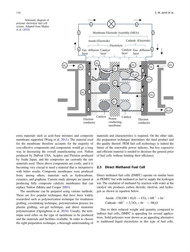
Fig. 3 Schematic diagram of
polymer electrolyte fuel cell
system. Adapted from Majlan
et al. (2018)
114
S. M. Jamil et al.
membrane supported (Wang et al. 2011). The material used
for the membrane therefore accounts for the majority of
cost-effective components and components would go a long
way in decreasing the overall manufacturing cost. Nafion
produced by DuPont USA, Aciplex and Flemion produced
by Asahi Japan, and the composites are currently the raw
materials used. These above components are costly, and it is
becoming very crucial to need a material that is inexpensive
with better results. Composite membranes were produced
from, among others, materials such as hydrocarbons,
ceramics, and graphene. Current study attempts are aimed at
producing fully composite catalytic membranes that can
replace Nafion (Mehta and Cooper 2003).
The membrane can be prepared using various methods.
There are five popular techniques that have been widely
researched such as polymerization technique for irradiation
grafting, crosslinking technique, polymerization process for
plasma grafting, sol–gel technique, and direct monomer
polymerization (Ogungbemi et al. 2019). Usually, the technique used relies on the type of membrane to be produced
and the materials and facilities available. In order to choose
the right preparation technique, a thorough understanding of
materials and characteristics is required. On the other side,
the preparation technique determines the final product and
the quality thereof. PEM fuel cell technology is indeed the
future of the renewable power industry, but less expensive
and efficient material is needed to decrease the general price
of fuel cells without limiting their efficiency.
2.3 Direct Methanol Fuel Cell
Direct methanol fuel cells (DMFC) operate on similar basis
as PEMFC but with methanol as fuel to supply the hydrogen
ion. The oxidation of methanol by reaction with water at the
catalyst site produces carbon dioxide, electron, and hydrogen as shown in equation below.
Anode : CH 3 OH þ H 2 O ! CO 2 þ 6H
þ
þ 6e
À
Cathode : 6H
þ
þ 3=2O 2 þ 6e
À
! 3H 2 O
Due to their reduced weight and quantity compared to
indirect fuel cells, DMFC is appealing for several applications. Solid polymers were shown as an appealing alternative
to traditional liquid electrolytes in this type of fuel cells.
H
+
H
+
H
+
H 2
e
-
e
-
e
-
e
-
e
-
e
-
O 2
H 2 O
H2O
O 2
O 2
H 2
H 2
Membrane Electrode Assembly (MEA)
Anode (Electrode)
Cathode (Electrode)
Electrolyte
Catalyst
layer
Catalyst
layer
Gas diffusion
layer
Gas diffusion
layer
Proton
conducting
membrane
Electron
conductor
Electron
conductor
Catalyst
Catalyst
e
-
e
-
e
-
e
-
e
-
e
-
O 2
H 2 O
H 2
Fig. 3 Schematic diagram of
polymer electrolyte fuel cell
system. Adapted from Majlan
et al. (2018)
114
S. M. Jamil et al.