

membrane followed by the removal of the polymer membrane leaving the ceramic material in the desired structure.
This removal can be achieved by heating the membrane at
high temperature to burn off the polymer material, or simply
by heating to the sintering temperature of the ceramic
material. The resulting material will then further heat to
sinter temperature to strengthen the structure of the ceramic.
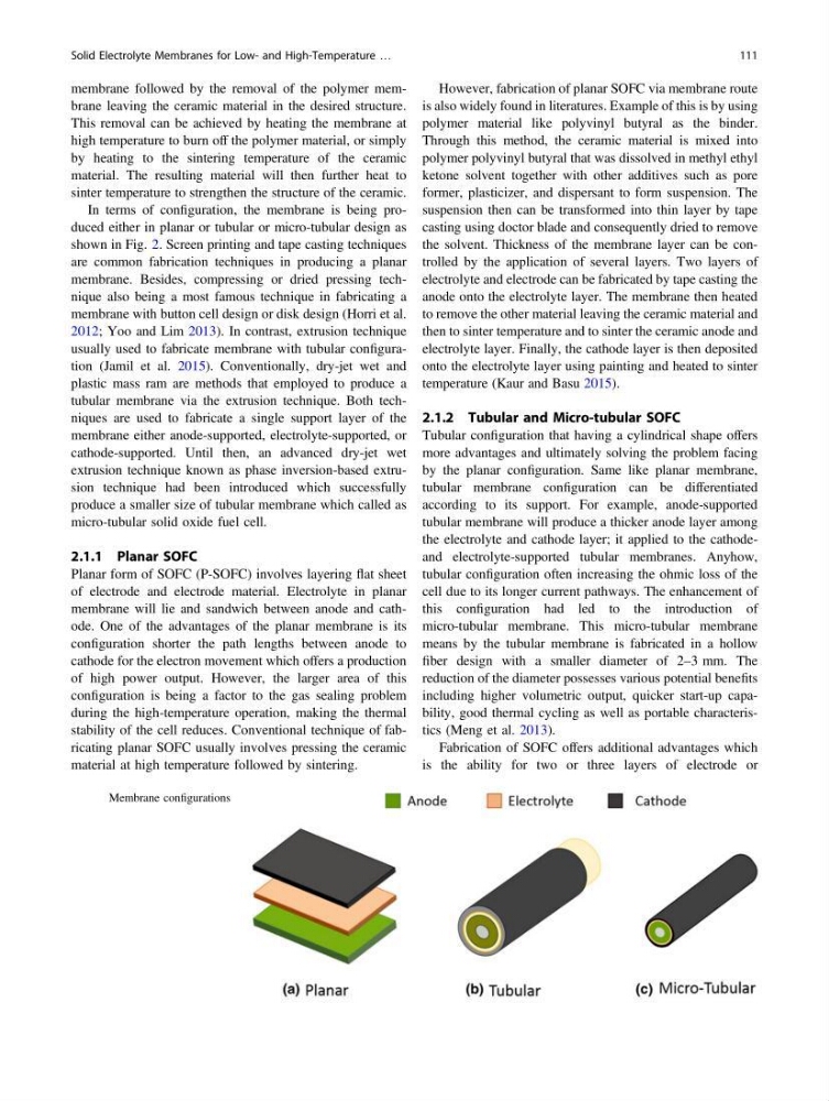
In terms of configuration, the membrane is being produced either in planar or tubular or micro-tubular design as
shown in Fig. 2. Screen printing and tape casting techniques
are common fabrication techniques in producing a planar
membrane. Besides, compressing or dried pressing technique also being a most famous technique in fabricating a
membrane with button cell design or disk design (Horri et al.
2012; Yoo and Lim 2013). In contrast, extrusion technique
usually used to fabricate membrane with tubular configuration (Jamil et al. 2015). Conventionally, dry-jet wet and
plastic mass ram are methods that employed to produce a
tubular membrane via the extrusion technique. Both techniques are used to fabricate a single support layer of the
membrane either anode-supported, electrolyte-supported, or
cathode-supported. Until then, an advanced dry-jet wet
extrusion technique known as phase inversion-based extrusion technique had been introduced which successfully
produce a smaller size of tubular membrane which called as
micro-tubular solid oxide fuel cell.
2.1.1 Planar SOFC
Planar form of SOFC (P-SOFC) involves layering flat sheet
of electrode and electrode material. Electrolyte in planar
membrane will lie and sandwich between anode and cathode. One of the advantages of the planar membrane is its
configuration shorter the path lengths between anode to
cathode for the electron movement which offers a production
of high power output. However, the larger area of this
configuration is being a factor to the gas sealing problem
during the high-temperature operation, making the thermal
stability of the cell reduces. Conventional technique of fabricating planar SOFC usually involves pressing the ceramic
material at high temperature followed by sintering.
However, fabrication of planar SOFC via membrane route
is also widely found in literatures. Example of this is by using
polymer material like polyvinyl butyral as the binder.
Through this method, the ceramic material is mixed into
polymer polyvinyl butyral that was dissolved in methyl ethyl
ketone solvent together with other additives such as pore
former, plasticizer, and dispersant to form suspension. The
suspension then can be transformed into thin layer by tape
casting using doctor blade and consequently dried to remove
the solvent. Thickness of the membrane layer can be controlled by the application of several layers. Two layers of
electrolyte and electrode can be fabricated by tape casting the
anode onto the electrolyte layer. The membrane then heated
to remove the other material leaving the ceramic material and
then to sinter temperature and to sinter the ceramic anode and
electrolyte layer. Finally, the cathode layer is then deposited
onto the electrolyte layer using painting and heated to sinter
temperature (Kaur and Basu 2015).
2.1.2 Tubular and Micro-tubular SOFC
Tubular configuration that having a cylindrical shape offers
more advantages and ultimately solving the problem facing
by the planar configuration. Same like planar membrane,
tubular membrane configuration can be differentiated
according to its support. For example, anode-supported
tubular membrane will produce a thicker anode layer among
the electrolyte and cathode layer; it applied to the cathodeand electrolyte-supported tubular membranes. Anyhow,
tubular configuration often increasing the ohmic loss of the
cell due to its longer current pathways. The enhancement of
this configuration had led to the introduction of
micro-tubular membrane. This micro-tubular membrane
means by the tubular membrane is fabricated in a hollow
fiber design with a smaller diameter of 2–3 mm. The
reduction of the diameter possesses various potential benefits
including higher volumetric output, quicker start-up capability, good thermal cycling as well as portable characteristics (Meng et al. 2013).
Fabrication of SOFC offers additional advantages which
is the ability for two or three layers of electrode or
Fig. 2 Membrane configurations
Solid Electrolyte Membranes for Low- and High-Temperature …
111
This removal can be achieved by heating the membrane at
high temperature to burn off the polymer material, or simply
by heating to the sintering temperature of the ceramic
material. The resulting material will then further heat to
sinter temperature to strengthen the structure of the ceramic.
In terms of configuration, the membrane is being produced either in planar or tubular or micro-tubular design as
shown in Fig. 2. Screen printing and tape casting techniques
are common fabrication techniques in producing a planar
membrane. Besides, compressing or dried pressing technique also being a most famous technique in fabricating a
membrane with button cell design or disk design (Horri et al.
2012; Yoo and Lim 2013). In contrast, extrusion technique
usually used to fabricate membrane with tubular configuration (Jamil et al. 2015). Conventionally, dry-jet wet and
plastic mass ram are methods that employed to produce a
tubular membrane via the extrusion technique. Both techniques are used to fabricate a single support layer of the
membrane either anode-supported, electrolyte-supported, or
cathode-supported. Until then, an advanced dry-jet wet
extrusion technique known as phase inversion-based extrusion technique had been introduced which successfully
produce a smaller size of tubular membrane which called as
micro-tubular solid oxide fuel cell.
2.1.1 Planar SOFC
Planar form of SOFC (P-SOFC) involves layering flat sheet
of electrode and electrode material. Electrolyte in planar
membrane will lie and sandwich between anode and cathode. One of the advantages of the planar membrane is its
configuration shorter the path lengths between anode to
cathode for the electron movement which offers a production
of high power output. However, the larger area of this
configuration is being a factor to the gas sealing problem
during the high-temperature operation, making the thermal
stability of the cell reduces. Conventional technique of fabricating planar SOFC usually involves pressing the ceramic
material at high temperature followed by sintering.
However, fabrication of planar SOFC via membrane route
is also widely found in literatures. Example of this is by using
polymer material like polyvinyl butyral as the binder.
Through this method, the ceramic material is mixed into
polymer polyvinyl butyral that was dissolved in methyl ethyl
ketone solvent together with other additives such as pore
former, plasticizer, and dispersant to form suspension. The
suspension then can be transformed into thin layer by tape
casting using doctor blade and consequently dried to remove
the solvent. Thickness of the membrane layer can be controlled by the application of several layers. Two layers of
electrolyte and electrode can be fabricated by tape casting the
anode onto the electrolyte layer. The membrane then heated
to remove the other material leaving the ceramic material and
then to sinter temperature and to sinter the ceramic anode and
electrolyte layer. Finally, the cathode layer is then deposited
onto the electrolyte layer using painting and heated to sinter
temperature (Kaur and Basu 2015).
2.1.2 Tubular and Micro-tubular SOFC
Tubular configuration that having a cylindrical shape offers
more advantages and ultimately solving the problem facing
by the planar configuration. Same like planar membrane,
tubular membrane configuration can be differentiated
according to its support. For example, anode-supported
tubular membrane will produce a thicker anode layer among
the electrolyte and cathode layer; it applied to the cathodeand electrolyte-supported tubular membranes. Anyhow,
tubular configuration often increasing the ohmic loss of the
cell due to its longer current pathways. The enhancement of
this configuration had led to the introduction of
micro-tubular membrane. This micro-tubular membrane
means by the tubular membrane is fabricated in a hollow
fiber design with a smaller diameter of 2–3 mm. The
reduction of the diameter possesses various potential benefits
including higher volumetric output, quicker start-up capability, good thermal cycling as well as portable characteristics (Meng et al. 2013).
Fabrication of SOFC offers additional advantages which
is the ability for two or three layers of electrode or
Fig. 2 Membrane configurations
Solid Electrolyte Membranes for Low- and High-Temperature …
111