

cationic groups; thus, most of the conductivity comes
from cation transport. The basic operations for AEM are
vice versa with CEM. Membrane structure could be
divided into two main structures of heterogeneous and
homogeneous. This classification depends on the degree of
heterogeneity of the membrane (Ariono et al. 2017).
Homogeneous membrane formed from a polymer, while
heterogeneous membrane formed from two different
polymers. Heterogeneous membranes are less expensive
compared to homogeneous membrane, but the composition
of these membranes is thicker with rough surface. Thus,
heterogeneous membrane is having higher resistance than
homogeneous membrane.
Essentially, for example, proton-exchange membrane fuel
cell (PEMFC) consists of porous composite of polymer
electrolyte binder and supported nanoparticle catalyst on
carbon particles (Litster and McLean 2004). Function of
polymer electrolyte binder is to provide ionic conductivity,
whereas electrical conductivity maintains by the carbon
support catalyst. Its electrode consists of carbon support
which acts as an electrical conductor; Pt particles as the
reaction site; Nafion ionomer which provides pathway for
proton conduction and Teflon binder which increases
hydrophobicity of the cell. Apart from that, gas diffusion
layer also important for PEM cell where it provides electrical
connection between the current collector and catalyst. This
layer must be thin and porous as well as electrically
conductive.
Direct methanol fuel cell (DMFC) usually will have a thin
membrane that is covered with sparse layer of platinum-base
catalyst on its both sides, which sandwiched between two
electrodes. A methanol solution introduces to the electrode
with negative charges. Typically, anode structure of DMFC
membrane composed of supported/unsupported catalyst
layers bonded with Nafion resin, Teflon-bonded carbon
black diffusion layer (GDL), and a carbon cloth or paper
diffusion layer (Allen et al. 2005). This type of fuel cell will
setup according to its Standard Newcastle flow bed-design
(Allen et al. 2005).
In contrast, solid oxide fuel cell (SOFC) membrane
usually comprises of thin and dense electrolyte, porous
asymmetric anode, and porous cathode. Thin electrolyte is
significant to transport the oxide ions from cathode to anode
while the dense structure is a must in order to ensure there is
no gas leaking or crossover between the fuel and the oxidizing agent. A porous asymmetric anode is meant by two
different structures that composed of anode layer that consists of finger-like void and sponge-like void. Finger-like
void is essential in providing a pathway for fuel to enter the
cell; sponge-like void gives a support to the whole cell and
also being sites for chemical reaction to take place. Porous
cathode will allow the oxidizing agent like oxygen or air to
pass through before entering the electrolyte.
2 Membranes Applications in Fuel Cells
Since all fuel cells involve the transfer or movement of ion
(O
2− in SOFC, H
+ in PEM and DMFC) in electrolyte
between anode and cathode; it is thus important to make the
electrolyte layer to be thin to reduce the distance needed for
the ion to travel but thick enough to separate the anode and
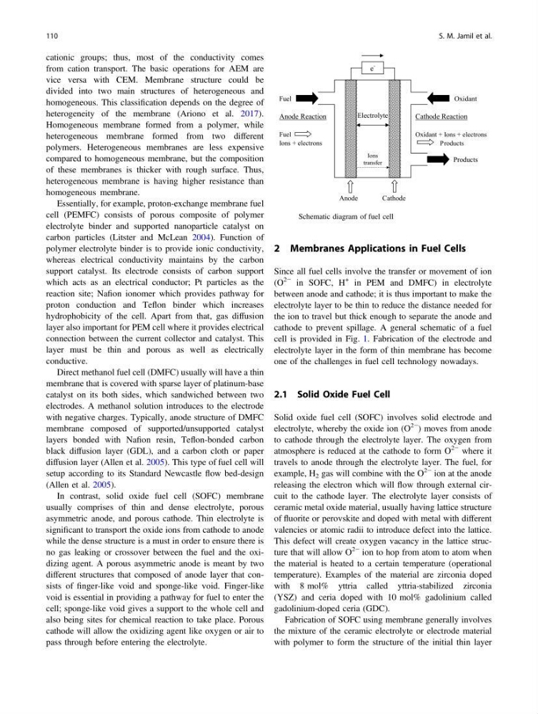
cathode to prevent spillage. A general schematic of a fuel
cell is provided in Fig. 1. Fabrication of the electrode and
electrolyte layer in the form of thin membrane has become
one of the challenges in fuel cell technology nowadays.
2.1 Solid Oxide Fuel Cell
Solid oxide fuel cell (SOFC) involves solid electrode and
electrolyte, whereby the oxide ion (O
2− ) moves from anode
to cathode through the electrolyte layer. The oxygen from
atmosphere is reduced at the cathode to form O
2− where it
travels to anode through the electrolyte layer. The fuel, for
example, H 2 gas will combine with the O
2− ion at the anode
releasing the electron which will flow through external circuit to the cathode layer. The electrolyte layer consists of
ceramic metal oxide material, usually having lattice structure
of fluorite or perovskite and doped with metal with different
valencies or atomic radii to introduce defect into the lattice.
This defect will create oxygen vacancy in the lattice structure that will allow O
2− ion to hop from atom to atom when
the material is heated to a certain temperature (operational
temperature). Examples of the material are zirconia doped
with 8 mol% yttria called yttria-stabilized zirconia
(YSZ) and ceria doped with 10 mol% gadolinium called
gadolinium-doped ceria (GDC).
Fabrication of SOFC using membrane generally involves
the mixture of the ceramic electrolyte or electrode material
with polymer to form the structure of the initial thin layer
Cathode Reaction
Oxidant + Ions + electrons
Products
e
-
Ions
transfer
Electrolyte
Anode
Cathode
Fuel
Oxidant
Products
Anode Reaction
Fuel
Ions + electrons
Fig. 1 Schematic diagram of fuel cell
110
S. M. Jamil et al.
from cation transport. The basic operations for AEM are
vice versa with CEM. Membrane structure could be
divided into two main structures of heterogeneous and
homogeneous. This classification depends on the degree of
heterogeneity of the membrane (Ariono et al. 2017).
Homogeneous membrane formed from a polymer, while
heterogeneous membrane formed from two different
polymers. Heterogeneous membranes are less expensive
compared to homogeneous membrane, but the composition
of these membranes is thicker with rough surface. Thus,
heterogeneous membrane is having higher resistance than
homogeneous membrane.
Essentially, for example, proton-exchange membrane fuel
cell (PEMFC) consists of porous composite of polymer
electrolyte binder and supported nanoparticle catalyst on
carbon particles (Litster and McLean 2004). Function of
polymer electrolyte binder is to provide ionic conductivity,
whereas electrical conductivity maintains by the carbon
support catalyst. Its electrode consists of carbon support
which acts as an electrical conductor; Pt particles as the
reaction site; Nafion ionomer which provides pathway for
proton conduction and Teflon binder which increases
hydrophobicity of the cell. Apart from that, gas diffusion
layer also important for PEM cell where it provides electrical
connection between the current collector and catalyst. This
layer must be thin and porous as well as electrically
conductive.
Direct methanol fuel cell (DMFC) usually will have a thin
membrane that is covered with sparse layer of platinum-base
catalyst on its both sides, which sandwiched between two
electrodes. A methanol solution introduces to the electrode
with negative charges. Typically, anode structure of DMFC
membrane composed of supported/unsupported catalyst
layers bonded with Nafion resin, Teflon-bonded carbon
black diffusion layer (GDL), and a carbon cloth or paper
diffusion layer (Allen et al. 2005). This type of fuel cell will
setup according to its Standard Newcastle flow bed-design
(Allen et al. 2005).
In contrast, solid oxide fuel cell (SOFC) membrane
usually comprises of thin and dense electrolyte, porous
asymmetric anode, and porous cathode. Thin electrolyte is
significant to transport the oxide ions from cathode to anode
while the dense structure is a must in order to ensure there is
no gas leaking or crossover between the fuel and the oxidizing agent. A porous asymmetric anode is meant by two
different structures that composed of anode layer that consists of finger-like void and sponge-like void. Finger-like
void is essential in providing a pathway for fuel to enter the
cell; sponge-like void gives a support to the whole cell and
also being sites for chemical reaction to take place. Porous
cathode will allow the oxidizing agent like oxygen or air to
pass through before entering the electrolyte.
2 Membranes Applications in Fuel Cells
Since all fuel cells involve the transfer or movement of ion
(O
2− in SOFC, H
+ in PEM and DMFC) in electrolyte
between anode and cathode; it is thus important to make the
electrolyte layer to be thin to reduce the distance needed for
the ion to travel but thick enough to separate the anode and
cathode to prevent spillage. A general schematic of a fuel
cell is provided in Fig. 1. Fabrication of the electrode and
electrolyte layer in the form of thin membrane has become
one of the challenges in fuel cell technology nowadays.
2.1 Solid Oxide Fuel Cell
Solid oxide fuel cell (SOFC) involves solid electrode and
electrolyte, whereby the oxide ion (O
2− ) moves from anode
to cathode through the electrolyte layer. The oxygen from
atmosphere is reduced at the cathode to form O
2− where it
travels to anode through the electrolyte layer. The fuel, for
example, H 2 gas will combine with the O
2− ion at the anode
releasing the electron which will flow through external circuit to the cathode layer. The electrolyte layer consists of
ceramic metal oxide material, usually having lattice structure
of fluorite or perovskite and doped with metal with different
valencies or atomic radii to introduce defect into the lattice.
This defect will create oxygen vacancy in the lattice structure that will allow O
2− ion to hop from atom to atom when
the material is heated to a certain temperature (operational
temperature). Examples of the material are zirconia doped
with 8 mol% yttria called yttria-stabilized zirconia
(YSZ) and ceria doped with 10 mol% gadolinium called
gadolinium-doped ceria (GDC).
Fabrication of SOFC using membrane generally involves
the mixture of the ceramic electrolyte or electrode material
with polymer to form the structure of the initial thin layer
Cathode Reaction
Oxidant + Ions + electrons
Products
e
-
Ions
transfer
Electrolyte
Anode
Cathode
Fuel
Oxidant
Products
Anode Reaction
Fuel
Ions + electrons
Fig. 1 Schematic diagram of fuel cell
110
S. M. Jamil et al.