

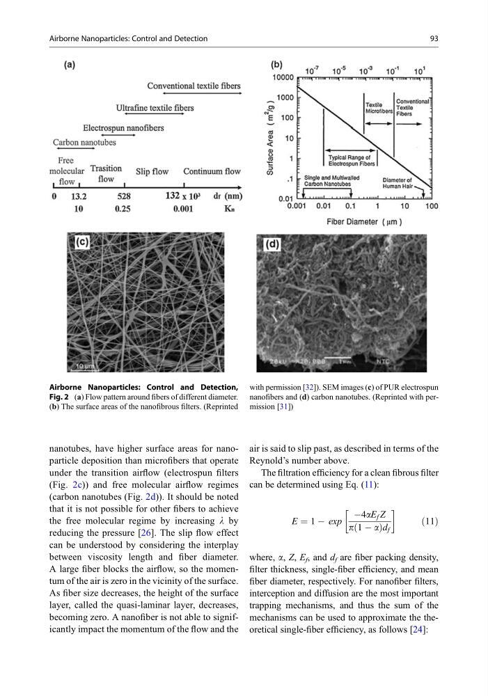
nanotubes, have higher surface areas for nanoparticle deposition than microfibers that operate
under the transition airflow (electrospun filters
(Fig. 2c)) and free molecular airflow regimes
(carbon nanotubes (Fig. 2d)). It should be noted
that it is not possible for other fibers to achieve
the free molecular regime by increasing l by
reducing the pressure [26]. The slip flow effect
can be understood by considering the interplay
between viscosity length and fiber diameter.
A large fiber blocks the airflow, so the momentum of the air is zero in the vicinity of the surface.
As fiber size decreases, the height of the surface
layer, called the quasi-laminar layer, decreases,
becoming zero. A nanofiber is not able to significantly impact the momentum of the flow and the
air is said to slip past, as described in terms of the
Reynold’s number above.
The filtration efficiency for a clean fibrous filter
can be determined using Eq. (11):
E ¼ 1 À exp
À4aE f Z
p 1 À a
ð
Þd f
!
ð11Þ
where, a, Z, E f , and d f are fiber packing density,
filter thickness, single-fiber efficiency, and mean
fiber diameter, respectively. For nanofiber filters,
interception and diffusion are the most important
trapping mechanisms, and thus the sum of the
mechanisms can be used to approximate the theoretical single-fiber efficiency, as follows [24]:
Airborne Nanoparticles: Control and Detection,
Fig. 2 (a) Flow pattern around fibers of different diameter.
(b) The surface areas of the nanofibrous filters. (Reprinted
with permission [32]). SEM images (c) of PUR electrospun
nanofibers and (d) carbon nanotubes. (Reprinted with permission [31])
Airborne Nanoparticles: Control and Detection
93
under the transition airflow (electrospun filters
(Fig. 2c)) and free molecular airflow regimes
(carbon nanotubes (Fig. 2d)). It should be noted
that it is not possible for other fibers to achieve
the free molecular regime by increasing l by
reducing the pressure [26]. The slip flow effect
can be understood by considering the interplay
between viscosity length and fiber diameter.
A large fiber blocks the airflow, so the momentum of the air is zero in the vicinity of the surface.
As fiber size decreases, the height of the surface
layer, called the quasi-laminar layer, decreases,
becoming zero. A nanofiber is not able to significantly impact the momentum of the flow and the
air is said to slip past, as described in terms of the
Reynold’s number above.
The filtration efficiency for a clean fibrous filter
can be determined using Eq. (11):
E ¼ 1 À exp
À4aE f Z
p 1 À a
ð
Þd f
!
ð11Þ
where, a, Z, E f , and d f are fiber packing density,
filter thickness, single-fiber efficiency, and mean
fiber diameter, respectively. For nanofiber filters,
interception and diffusion are the most important
trapping mechanisms, and thus the sum of the
mechanisms can be used to approximate the theoretical single-fiber efficiency, as follows [24]:
Airborne Nanoparticles: Control and Detection,
Fig. 2 (a) Flow pattern around fibers of different diameter.
(b) The surface areas of the nanofibrous filters. (Reprinted
with permission [32]). SEM images (c) of PUR electrospun
nanofibers and (d) carbon nanotubes. (Reprinted with permission [31])
Airborne Nanoparticles: Control and Detection
93